
Eureka
For R&D, Eureka makes reading and utilizing patents & technical documents easy.
Eureka AIR
Designed for self-driven R&D workflows. Generate viable solutions, solve complex R&D challenges, empower your innovation with AI.

Eureka Materials
Designed for material experts only. Revolutionize your material R&D, from search, analyze, to developing new materials.

TechResearch
Generate reliable direction feasibility study reports for your R&D in just a few steps.

TechSeek
Discover and master advanced knowledge NOW. Basics, ideas, possibilities, all at once.

TechMind
As an expert in R&D Theories, TechMind can generates customized viable solutions instantly.

TechRisk
Analyze your overall solution with one click, know your potential R&D risks in advance.

TechMonitor
Get weekly tech updates, stay abreast of the latest tech innovations and key insights.
Selective plating device
An electroplating device and selective technology, applied in plating baths, circuits, semiconductor devices, etc., to reduce material waste, reduce pollution, and improve efficiency
- Summary
- Abstract
- Description
- Claims
- Application Information
AI Technical Summary
Problems solved by technology
Method used
Image

Examples
Embodiment 1
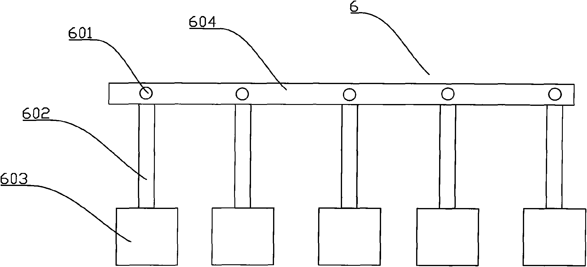
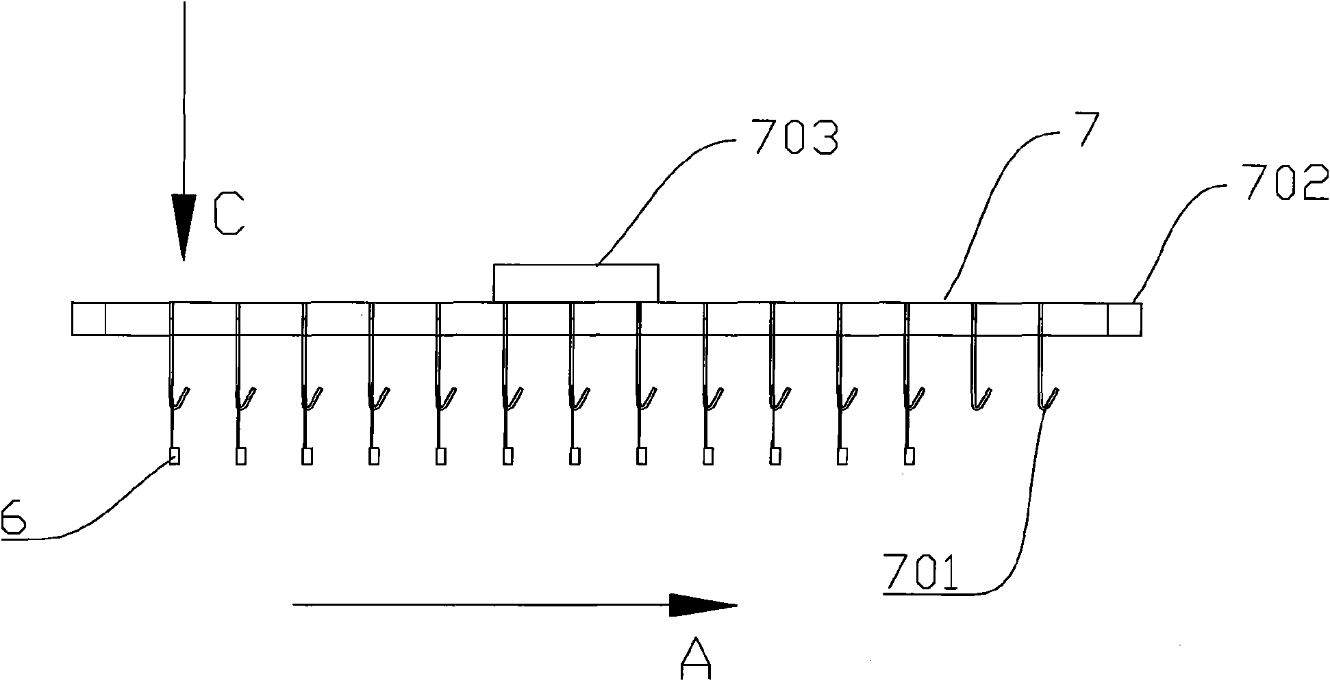
[0044] Selective plating devices such as image 3 , Figure 4 As shown, the hook support frame 7 includes two parallel frames 702 and a beam 703, the two frames 702 are connected as a whole through the beam 703, the beam 703 exceeds a part of the frame 702, and the conductive hook 701 is installed on the frame 702. A group of hooks 701 are respectively located on the two frames 702, and the two hooks are arranged in a straight line to form a group to hang a lead frame. The number of the hooks 701 is more than two groups, and more than two groups of the hooks 701 are arranged along the direction parallel to the liquid surface of the electroplating solution, that is, the A direction in the figure, and the number of groups of the hooks can be determined according to actual production needs.
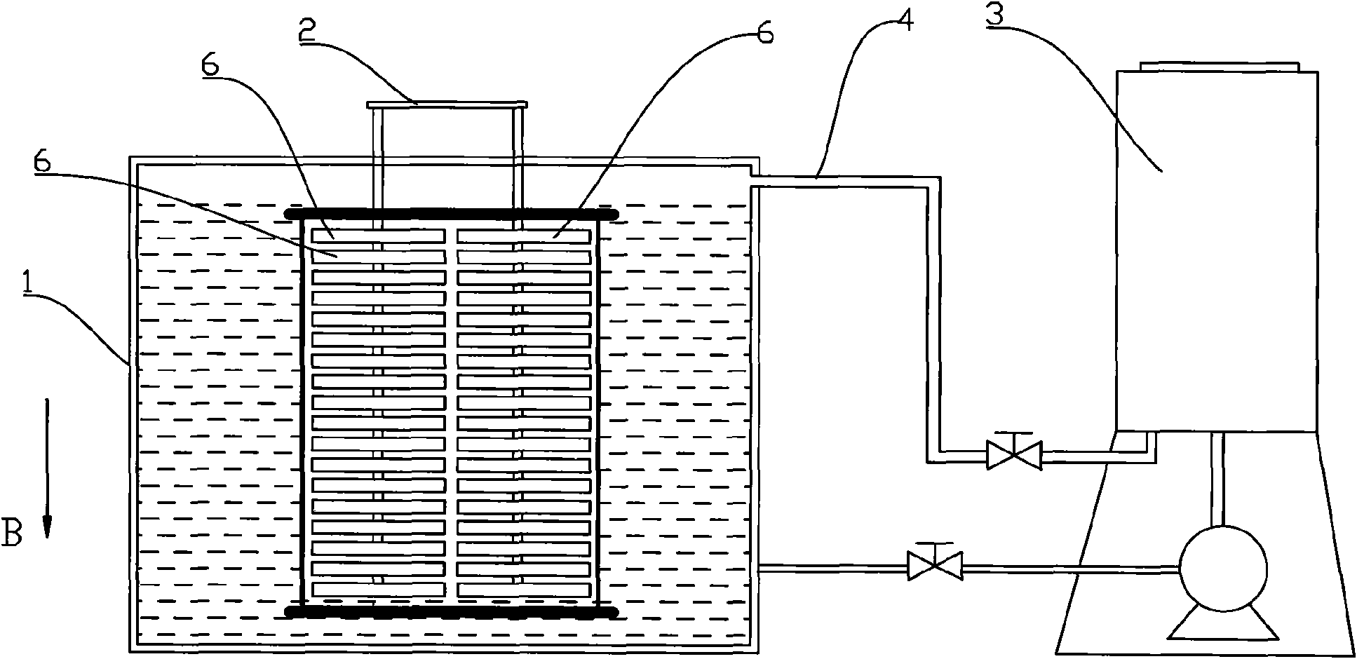
[0045] Such as Figure 5 As shown, the electroplating solution tank 5 is also included, and the part of the beam 703 beyond the frame 702 is mounted on the tank wall of the electroplating ...
Embodiment 2
[0048] It differs from Example 1 in that, as Figure 8 As shown, an overflow hole 506 is provided on the wall of the electroplating solution tank 5, and the overflow hole 506 replaces the overflow tank of the first embodiment, and the rest of the structure is the same as that of the first embodiment.
Embodiment 3
[0050] It differs from Example 1 in that, as Figure 9 As shown, the number of beams 703 is two, and the two beams 703 can ensure the stable placement of the entire frame and reduce shaking, and the rest of the structure is the same as that of Embodiment 1.
[0051] The number of beams 703 can also be adjusted according to actual needs.
PUM
 Abstract
Description
Claims
Application Information
 - R&D Engineer
- R&D Manager
- IP Professional
- Industry Leading Data Capabilities
- Powerful AI technology
- Patent DNA Extraction
Browse by: Latest US Patents, China's latest patents, Technical Efficacy Thesaurus, Application Domain, Technology Topic, Popular Technical Reports.
© 2024 PatSnap. All rights reserved.Legal|Privacy policy|Modern Slavery Act Transparency Statement|Sitemap|About US| Contact US: help@patsnap.com