Cloth-rolling device of weaving machine

A loom and cloth rolling technology, which is applied in looms, textiles, textiles and papermaking, etc., can solve the problems of high price, high tension of cloth rolling, slow speed of cloth rolling roller, etc., and achieves simple structure, convenient installation and maintenance , low-cost effect

Inactive Publication Date: 2009-10-07
SUZHOU UNIV
View PDF2 Cites 9 Cited by
  • Summary
  • Abstract
  • Description
  • Claims
  • Application Information

AI Technical Summary

Problems solved by technology

In order to achieve the above design indicators, the cloth winding device needs to solve the following problems: First, the length of the fabric woven by the loom per unit time is affected by many factors and is not constant, so the cloth volume per unit time of the cloth winding roller is not constant. Constant; second, during the cloth rolling process, the diameter of the cloth roll gradually increases, so that the length of the cloth wound by the cloth winding roller per revolution also gradually increases, and the corresponding cloth winding roller speed must gradually decrease. Third, in order to keep the tension of the cloth basically constant during the cloth rolling process, the driving torque on the cloth rolling roller must increase with the increase of the cloth roll diameter
However, there are various types of fabrics woven by looms. When weaving light and thin fabrics such as silk, the tension of the fabric should be small, otherwise the fabric will be damaged; when weaving heavy fabrics such as denim, the tension of the fabric should be large, otherwise the cloth The fabric in the roll will wrinkle and affect the post-processing of the fabric
However,

Method used


Image

  • Cloth-rolling device of weaving machine
  • Cloth-rolling device of weaving machine
  • Cloth-rolling device of weaving machine

Examples


Embodiment 1

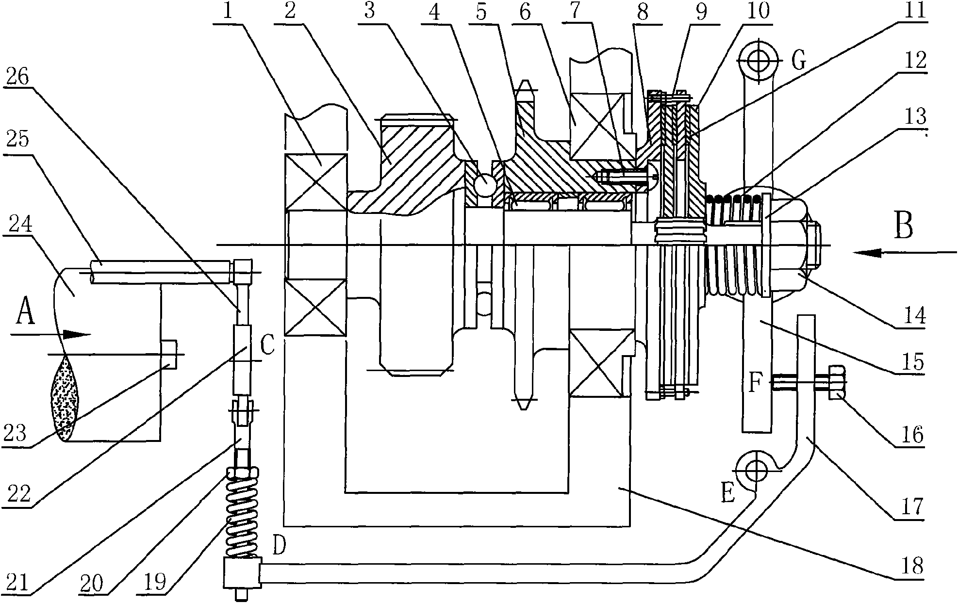
[0025] See attached figure 1, the specific embodiment of the input shaft, the output shaft and the friction clutch between the two shafts in the present embodiment is as follows: the input shaft 2 is driven by the main shaft of the loom; not shown) and other drives; the hollow output shaft 5 is looped on the input shaft 2 through the needle roller bearing 4, and the axes of the two shafts coincide and can rotate relatively; the active friction disc 10 of the friction clutch is connected with the input shaft 2 through a spline, It can move axially on the input shaft 2; the driven friction disc 8 of the friction clutch is fixedly connected with the output shaft 5 with the connecting screw 7, and the rest of the driven friction discs are fixed circumferentially relative to the driven friction disc 8 through the guide pin 9, but can be moved along the The guide pin 9 moves axially; the friction plate 11 is clamped by the main and driven friction discs, and the friction force is tr...


PUM


Abstract

The invention discloses a cloth-rolling device of a weaving machine, which consists of a friction clutch connected with an input shaft and an output shaft, a cloth roll diameter detection mechanism, a loading mechanism and the like. In the cloth roll diameter detection mechanism, a cloth-pressing roller jointed with a cloth roll by compression is movably hinged with a swing link of the cloth-pressing roller, the swing link of the cloth-pressing roller is fixedly connected with a part of a cam, a cam carrier props against the part of the cam, a pressure spring is sheathed on the cam carrier, one end of the pressure spring props against an adjusting nut and the other end thereof props against a force-amplifying lever; and in the loading mechanism, one end of the force-amplifying lever is in gap junction with the cam carrier while the other end thereof is provided with an adjusting screw with adjustable position, the terminal of the adjusting screw props against a loading bar which is movably hinged with a fixed shaft, and loading power is transmitted to an active friction disc of the friction clutch by a loading bearing. The cloth-rolling device has simple structure, convenient manufacture, installation and maintenance, and low cost; and the fabric tension is controllable when the cloth roll is formed by winding, thus being beneficial to preventing the fabric in the cloth roll from creasing and beneficial to the post process of the fabric.

Description

technical field [0001] The invention relates to an in-machine cloth rolling device of a loom, in particular to a method and mechanism for adjusting the tension of the cloth rolling, belonging to the technical field of textile machinery. Background technique [0002] The cloth rolling device of the loom is a special device that must be equipped with each loom. Its function is to wind the fabric that has been woven by the loom on the cloth rolling roller in a regular manner, so as to avoid the disorderly accumulation of fabrics that will affect the operation of the operator and cause fabric damage. stained, wrinkled or damaged. The main design index of the cloth rolling device is that both ends of the cloth roll are neat, there is no wrinkle in the middle, and the tension of each layer of cloth in the cloth roll is basically the same. It is conducive to the weaving of fabrics and the improvement of fabric quality, and at the same time it can facilitate post-processing such as...

Claims


Application Information

Patent Timeline
IPC IPC(8): D03D49/20
Inventor 钱志良秦乐宁
Owner SUZHOU UNIV
Why Eureka
Try Eureka