A self-supplied magnetic current damper

A magneto-rheological damper and variable damper technology, applied in vibration suppression adjustment, non-rotational vibration suppression, etc., can solve problems such as broken wires, low energy conversion efficiency, and oil leakage

Inactive Publication Date: 2009-10-07
CHONGQING UNIV
View PDF1 Cites 60 Cited by
  • Summary
  • Abstract
  • Description
  • Claims
  • Application Information

AI Technical Summary

Problems solved by technology

[0003] Usually, the electric energy of the magnetorheological damper is provided externally. For example, in a car, it is powered by a battery. Magnetic flow damper failure
In addition, the magnetorheological damper depends on the supply of external power supply, and cannot work in some occasions where the external power supply cannot be provided. If the external power supply fails, the magnetorheological damper will also fail to work
[0004] Based on the above deficiencies, in recent years, researchers in this field have also proposed self-powered technical solutions. The US patent (US20080053763) proposed a permanent magnet moving iron principle structure, which uses the permanent magnet on the spring vibrator to cut up and down. The magnetic field lines generate induced electromotive force to power the magnetorheological damper. Due to the large size and low energy conversion efficiency of this solution, it is difficult to integrate it into the magnetorheological damper and provide enough electric energy for the magnetorheological damper to work, and the patent also Does not involve energy storage and management, there are many deficiencies

Method used


Image

  • A self-supplied magnetic current damper
  • A self-supplied magnetic current damper
  • A self-supplied magnetic current damper

Examples


Embodiment Construction

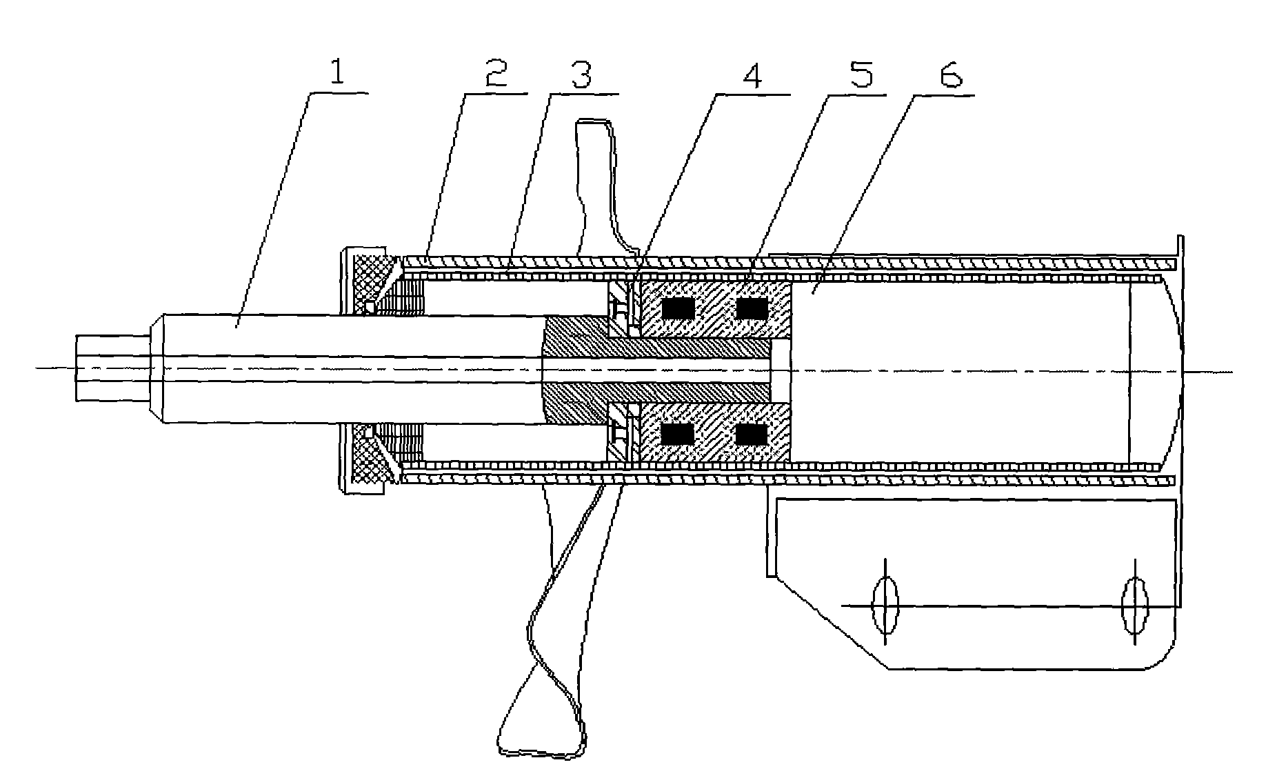
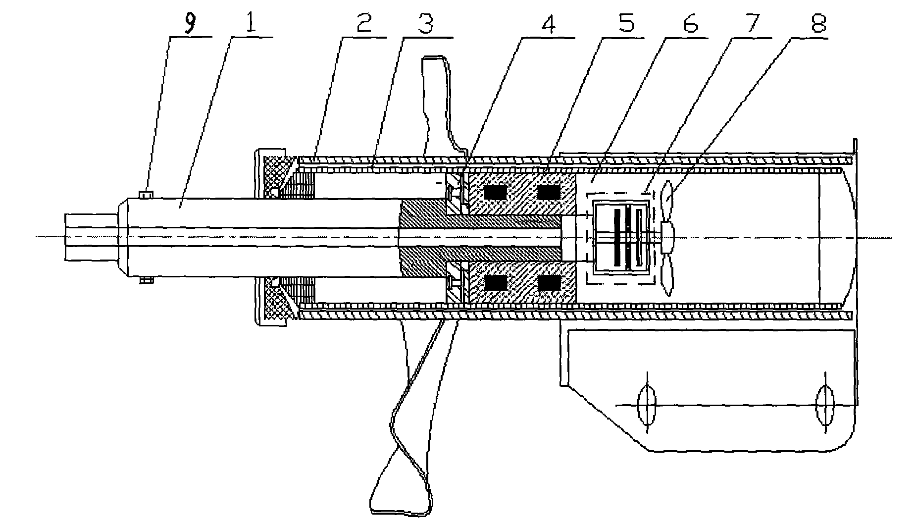
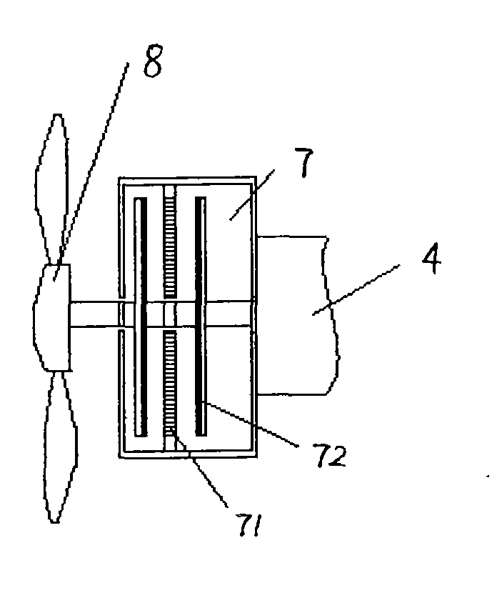
[0019] see figure 2 , The self-supplied electromagnetic rheological damper is composed of a magnetorheological damper and a vibration energy harvester, which can realize the self-supply of the working power of the magnetorheological damper. The vibration energy harvester adopts a multi-blade disc electromagnetic structure, see Figure 3A with Figure 3B , the vibration energy harvester is composed of multiple impellers 8 and disc-shaped magnetoelectric transducers 7, and is installed at the bottom of the piston 4 of the magnetorheological damper. Other structures of the magnetorheological damper are the same as figure 1 Basically be the same, 9 is the limiting device that increases. The structure of the rotor 72 and the stator 71 of the disc magnetoelectric transducer 7 is shown in Figure 4 , the permanent magnet material selects rare earth permanent magnets with high magnetic energy product and high coercive force, such as Nd-Fe-B rare earth permanent magnets (the maximu...


PUM


Abstract

The invention presents a self-supplied magnetic current damper, which includes a magnetic current damper, a vibration energy collector, and an energy storage management module. The energy collector is a multi-vane disc shaped electro-magnetism type mechanical energy collector installed on the piston bottom of the magnetic current damper, which is composed of multiple impellers and disc shaped magnetoelectric transducers, wherein, the disc shaped magnetoelectric transducers are mounted on the piston, the multiple impellers are mounted on the rotor of the disc shaped magnetoelectric transducers, and the energy produeced by the disc shaped magnetoelectric transducers is lead out by the coil on the stator. The output lines of the disc shaped magnetoelectric transducers are connected to the energy storage management module, and the output of the energy storage management module is connected to the magnetizing coil of the magnetic current damper. During work, the magnetic current liquid impacts the vanes, the impeller converts the fluid washing into the rotation of the disc shaped stator inlaid on the rare-earth permanent magnet, the magnetic flux of the coil on the disc shaped stator is changed, in order to achieve effective collection of mechanical energy, and greatly reduce the transducer volume.

Description

technical field [0001] The invention belongs to the magneto-rheological damper technology. Background technique [0002] The structure of the magnetorheological damper is as follows figure 1 As shown, when the controlled object vibrates, the piston rod 1 and the piston 4 move in the working cylinder 6, and the working cylinder 6 is filled with magnetorheological fluid. Since the liquid has continuity and incompressibility, according to the Navier-Stokes equation, substitute From the constitutive equation of the magnetorheological fluid, it can be deduced that there is a huge pressure difference between the two ends of the narrow damping channel between the piston 4 and the working cylinder inner cylinder 3 (2 is the working cylinder outer cylinder). Under the action of pressure, the magnetorheological fluid will flow at high speed in the working chamber of the damper. When the coil 5 is supplied with exciting current, a magnetic field will be generated in the damping chann...

Claims


Application Information

Patent Timeline
Patent Type & Authority Applications(China)
IPC IPC(8): F16F9/53
Inventor 余淼李敏王四棋董小闵
Owner CHONGQING UNIV
Why Eureka
Try Eureka