On-orbit car wheel lathe being capable of processing multiunit wheels simultaneously

A wheel lathe and wheel technology, which is applied to metal processing equipment, turning equipment, turning equipment, etc., can solve the problems of insufficient rigidity of machine tools, affecting processing accuracy, uneven force on friction rollers, etc., to improve processing efficiency and improve processing accuracy. , The effect of reducing the geometric size error

Inactive Publication Date: 2009-10-14
孙文学
View PDF0 Cites 12 Cited by
  • Summary
  • Abstract
  • Description
  • Claims
  • Application Information

AI Technical Summary

Problems solved by technology

[0006] The second mode "non-drop wheel lathe" wheel set rotation drive method has defects
This transmission method has the following two disadvantages: one is to affect the machining accuracy
The friction between the friction roller and the tread surface of the processing wheel drives the wheel to rotate. The friction surface is the processing surface of the operation. As the processing progresses, the contact surface changes, and the friction roller is bound to generate vibration. At the same time, the force of each friction roller is not Even, it is not conducive to the stable operation of the machine tool and affects the machining accuracy
The second is that as the processing progresses, the contact surface changes, and the friction force between the friction roller and the wheel pair changes, which is prone to slipping
[0011] At present, the left and right tool rests of the domestic non-falling wheel set lathe are separately installed on the left and right bed bodies through the tool post columns on each side, but the left and right bed bodies are only connected by the lower connecting beam and the upper "open" "U" "Type structure makes the overall rigidity of the machine tool insufficient
Moreover, the separation of the left and right tool holders makes the design, manufacture, assembly and geometric accuracy detection of the machine tool lack a scientific, unified and perfect benchmark, which is also not conducive to the installation and adjustment of the machine tool at the user's site

Method used


Image

  • On-orbit car wheel lathe being capable of processing multiunit wheels simultaneously

Examples


Embodiment Construction

[0027] The present invention will be described in detail below with reference to the accompanying drawings.

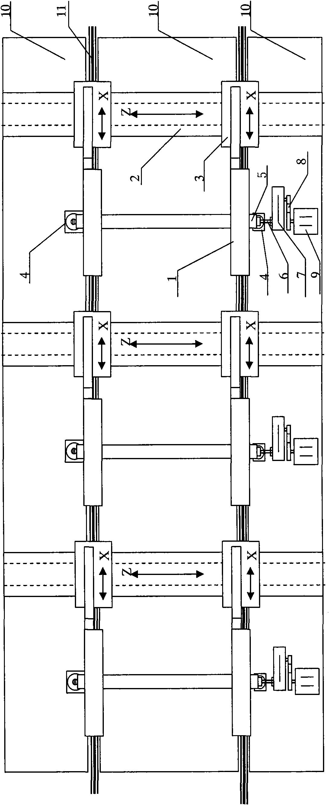
[0028] Overall structure: The flat bed 12 is the basic structural part of the machine tool, on which other components such as the hydraulic system, the main transmission system, and the numerical control system of the tool post are placed on it, and it is used as a process benchmark to ensure machining accuracy. 13 is a steel rail, and the rolling stock to be processed is drawn from the steel rail to the designated position of the lathe to stay.

[0029] Main drive system: mainly composed of motor, pulley, cardan shaft and other components. The three-phase AC motor 6 transmits the power to the gearbox 8 through the pulley 7, and after the gearbox is decelerated, it is output by the output flange of the gearbox, and the power is transmitted to the connecting flange connected to the main shaft through the universal coupling 9. Joint 10 directly drives wheel pair 11 to r...


PUM


Abstract

An on-orbit car wheel lathe being capable of processing multiunit wheels simultaneously relates to a machine tool, comprises a main transmission system, a hydraulic system and a tool support system and is characterized in that the hydraulic system, the main transmission system and the tool support system are all placed on a plane lathe body thereof; the plane lather body is the foundation structure element of the machine tool; a rolling stock to be processed is drawn into the plane lathe body from rail steels; the main transmission system comprises a motor, a belt pulley, and a cardan spindle unit; the hydraulic system comprises a hydraulic station, an ail line, and a hydraulic pressure axle box supporting centering device; every group of wheel pair tool support system comprises two groups of tool rests. The on-orbit car wheel lathe processes a plurality of groups of wheel pairs simultaneously, which can obviously increase processing working performance, and simultaneously as each wheel pair is located on the same processing benchmark platform, the geometric dimension difference among the wheel pairs of the same lathe body (or the same bogie) can be increased.

Description

technical field [0001] The invention relates to a processing machine tool, in particular to a lathe for processing wheels of multiple sets of railway locomotive vehicles in an on-rail manner. Background technique [0002] The existing railway rolling stock wheel processing lathe has two modes. [0003] The first is the traditional model horizontal wheel lathe. During maintenance, the wheel set is disassembled, and the wheel set is hoisted to the lathe by a crane for profile cutting of the wheel tread. This traditional wheel lathe is suitable for large and medium repairs of locomotives, because the wheel sets (one axle and two wheels) must be removed for maintenance according to the scope and process of large and medium repairs, and during large and medium repairs, especially During the overhaul, the general wheel set has reached or is close to the forbidden limit. The wheel set cannot continue to be used for a medium maintenance period and the wheel hub or handle must be r...

Claims


Application Information

Patent Timeline
Patent Type & Authority Applications(China)
IPC IPC(8): B23B5/04
Inventor 孙文学
Owner 孙文学
Why Eureka
Try Eureka