
Water-saving valve for balancing flow

A water-saving valve and flow technology, applied in the field of water delivery valve, can solve problems such as affecting users' water intake, waste, and large water output.

Inactive Publication Date: 2013-07-10
胡东白
View PDF0 Cites 0 Cited by
  • Summary
  • Abstract
  • Description
  • Claims
  • Application Information

AI Technical Summary

Problems solved by technology

For the same water pipe diameter, the higher the water pressure, the greater the water output; the water pressure is too small, the water supply is insufficient, affecting the user's water intake; the water pressure is too high, the water output is too large, and it is easy to cause waste

Method used


Image

  • Water-saving valve for balancing flow
  • Water-saving valve for balancing flow
  • Water-saving valve for balancing flow

Examples


Embodiment 1

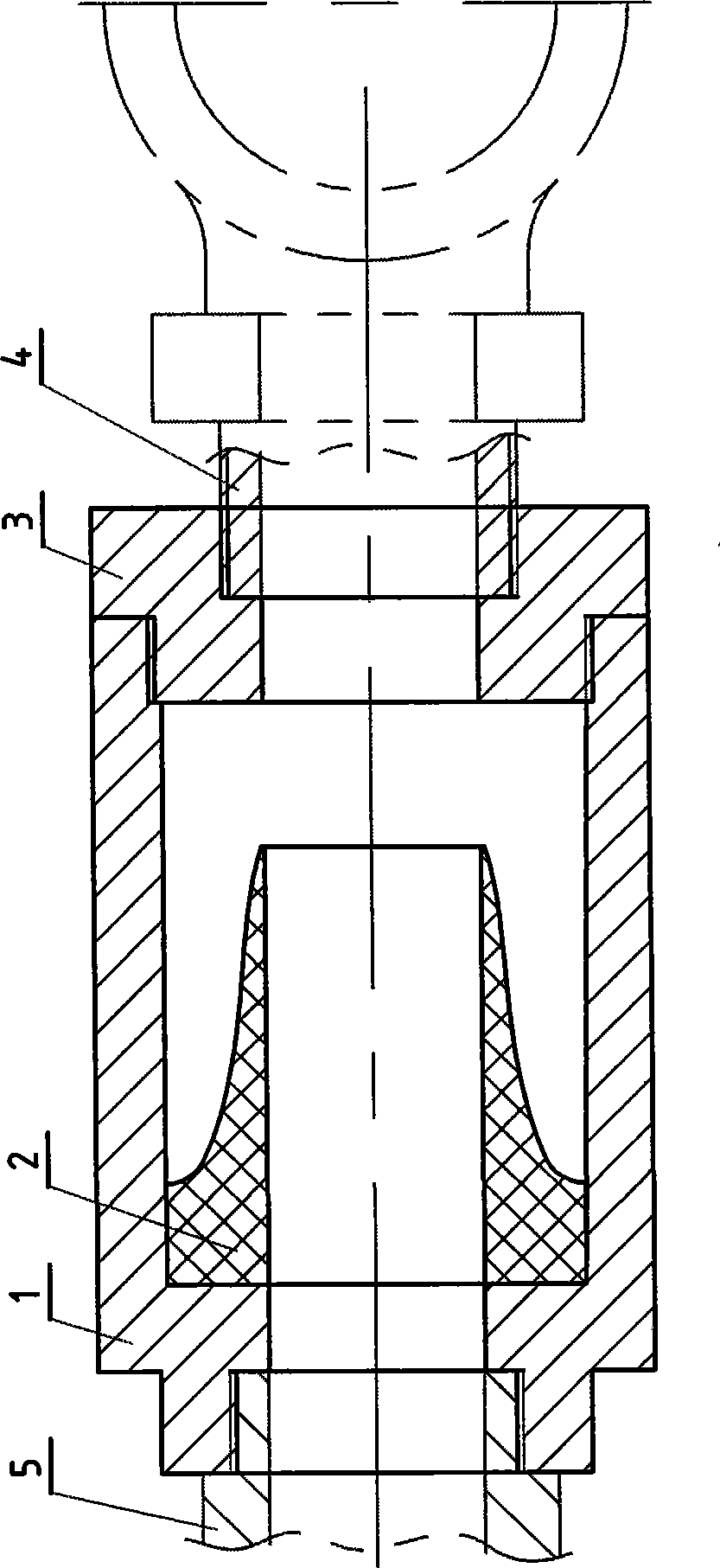
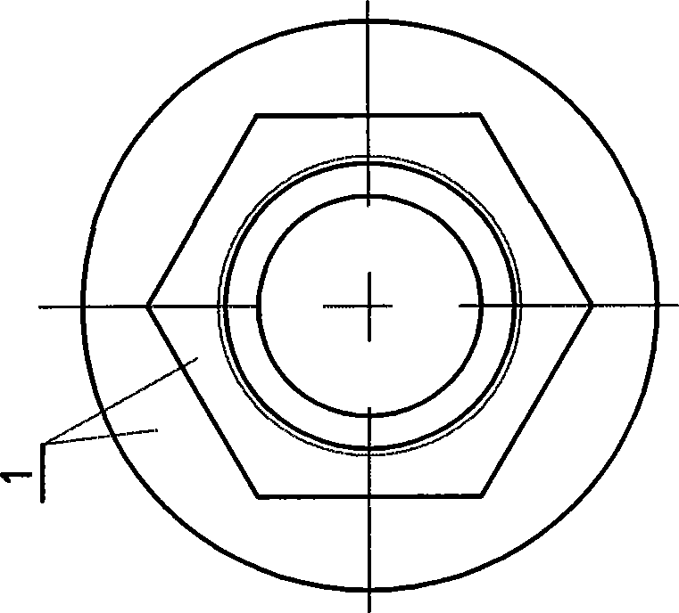
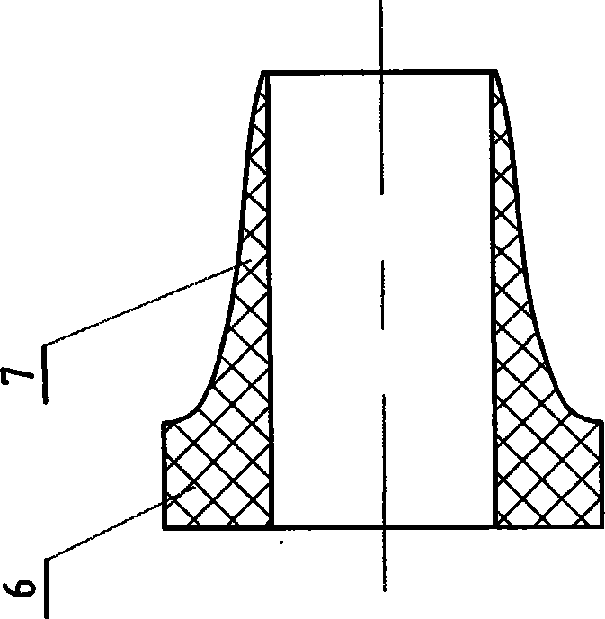
[0011] Example 1 as Figure 1-4 As shown: a water-saving valve with balanced flow is composed of a cylindrical valve body 1, a soft silicone rubber elastic valve 2 and a reducing joint 3; the soft silicone rubber elastic valve 2 is connected by a hollow ring 6 and a hollow conical truncated truncated As a whole, the hollow ring 6 communicates with the inner hole of the long hollow truncated cone 7 with equal diameters, the pitch line of the hollow truncated cone 7 is a concave parabola, and the wall thickness of the small end ring hole of the hollow truncated cone 7 is small; the cylindrical valve body 1 The inner cavity is matched with the outer wall of the ring of the soft silicon rubber elastic valve 2, and the inner thread of the cylindrical valve body 1 with the protruding platform is connected with the external thread of the matching B water pipe joint 5; the cylindrical valve body 1 The inner hole thread at the other end is mated with the outer thread at one end of the ...

Embodiment 2

[0013] Example 2 as Figure 5 Shown: a hollow circular soft silicone rubber elastic valve 8 matched with the water-saving valve of balanced flow described in Embodiment 1, its vertical section line is a convex parabola, and the hollow circular soft silicon rubber elastic valve The wall thickness of the small end ring hole of 8 is relatively large.

Embodiment 3

[0014] Embodiment 3 In order to ensure the quality of life of residents, it is required that the pressure of tap water entering the household is not less than 0.7MPa. A seven-story building is set up with a floor height of 3 meters. The pressure on the first floor is: 0.7+3×7×0.1=2.8MPa; therefore, the water supply pressure of the tap water pipe network on the first floor is four times that of the tap water entering the house on the seventh floor.

[0015] Water flow = flow velocity × cross-sectional area of ​​water flow;

[0016] Flow rate = flow coefficient × fluid density × pressure;

[0017] The flow rate is proportional to the pressure when the flow coefficient (same shape and smoothness) and fluid density (same substance) are constant.

[0018] The caliber of the tap water pipes entering the house is generally 25mm. In the same unit of time, the flow out of the water pipes of the same caliber is four times that of the first floor as that of the seventh floor.

[0019] ...


PUM


Abstract

The invention relates to a water-saving valve for balancing flow, and the valve comprises a cylindrical valve body, a feather valve and a reducing joint; the feather valve is connected with a hollow cirque and a hollow frustum as a whole; the inner holes of the hollow cirque and the hollow frustum are the same in diameter and communicated with each other; one end of the inner cavity of the cylindrical valve body is a ladder-type truncated cone matched with the outer wall of the feather valve; the internal threads of an inner hole at the inner cavity end head of the cylindrical valve body provided with the ladder-type truncated cone are matched and connected with the external threads of a supporting water pipe connector; the internal threads of an inner hole at the other inner cavity end head are matched and connected with the external threads of one end of the reducing joint; and the internal threads of the other end of the reducing joint are matched and connected with the external threads of a supporting water meter joint. If the water-saving valve for balancing flow is arranged on the entering end of a tap water inlet pipe of a floor in which a user lives or the outlet ends of water measuring instruments of users in each floor, the feather valve can automatically shrink the drift diameter of a water transmission hole with the rising of water pressure, maintain proper flow andcan control waste due to overhigh water pressure and overlarge flow in the bottom floor.

Description

technical field [0001] The invention relates to a water delivery valve, in particular to a water saving valve with balanced flow. Background technique [0002] The bottom water pressure of the traditional building tap water pipe network supply system is the largest, and the higher the floor, the lower the water pressure. For the same water pipe diameter, the higher the water pressure, the greater the water output; if the water pressure is too low, the water supply will be insufficient, which will affect the user's water intake; if the water pressure is too high, the water output will be too large, which will easily lead to waste. Contents of the invention [0003] The object of the present invention is to provide a water-saving valve capable of balancing the flow of running water on each floor. [0004] In order to solve the above technical problems, the technical solution of the present invention is: a water-saving valve with balanced flow is composed of a cylindrical va...

Claims


Application Information

Patent Timeline
Patent Type & Authority Patents(China)
IPC IPC(8): F16K47/16F16K27/00F16L15/00
Inventor 胡东白
Owner 胡东白
Learn More