
Sand discharging device of sand silo

A technology for sand bins and bin walls, which is applied in the field of storage and discharge devices for sand materials, and can solve problems such as inability to realize switching actions, fast flow speed, and deformation of mandrel mold shells, etc.

Pending Publication Date: 2022-05-06
黄山中发耐磨材料科技股份有限公司
View PDF2 Cites 0 Cited by
  • Summary
  • Abstract
  • Description
  • Claims
  • Application Information

AI Technical Summary

Problems solved by technology

[0004] The straight-up and straight-down sand discharge method of the above-mentioned sand discharge device is not only the layout of almost all prior art sand discharge outlets, but also the design idea of ​​the sand retaining valve is almost the same as the gate valve structure. In addition, the gate valve plate and the outlet The sand mouth is a dense and compact structure. Therefore, the above-mentioned sand release plan will inevitably lead to blockage of sand flow rate, which is extremely harmful in the process of packing the sand box. The direct vertical sand fall not only has a large flow rate and a fast flow rate, but if coupled with When there are bends or other sand filling areas that cause large sand resistance between the mandrel shell and the sand box, the basic requirements for filling cannot be achieved at all, and serious cases will lead to deformation or even damage of the mandrel shell during casting. Serious consequences of liquid leakage; the basic prospect of the precise cooperation between the gate valve and the sand outlet is extremely attractive, but the reality is also extremely cruel, because a slight deformation of the gate valve plate will lead to difficulty in its switching action or even impossible switching action, that is, the gate valve structure It must provide extremely high enclosure costs, which does not include once sand is splashed into the guide rails that limit the displacement direction of the gate valve plate, and the switching action cannot be realized.

Method used


Image

  • Sand discharging device of sand silo
  • Sand discharging device of sand silo
  • Sand discharging device of sand silo

Examples


Embodiment Construction

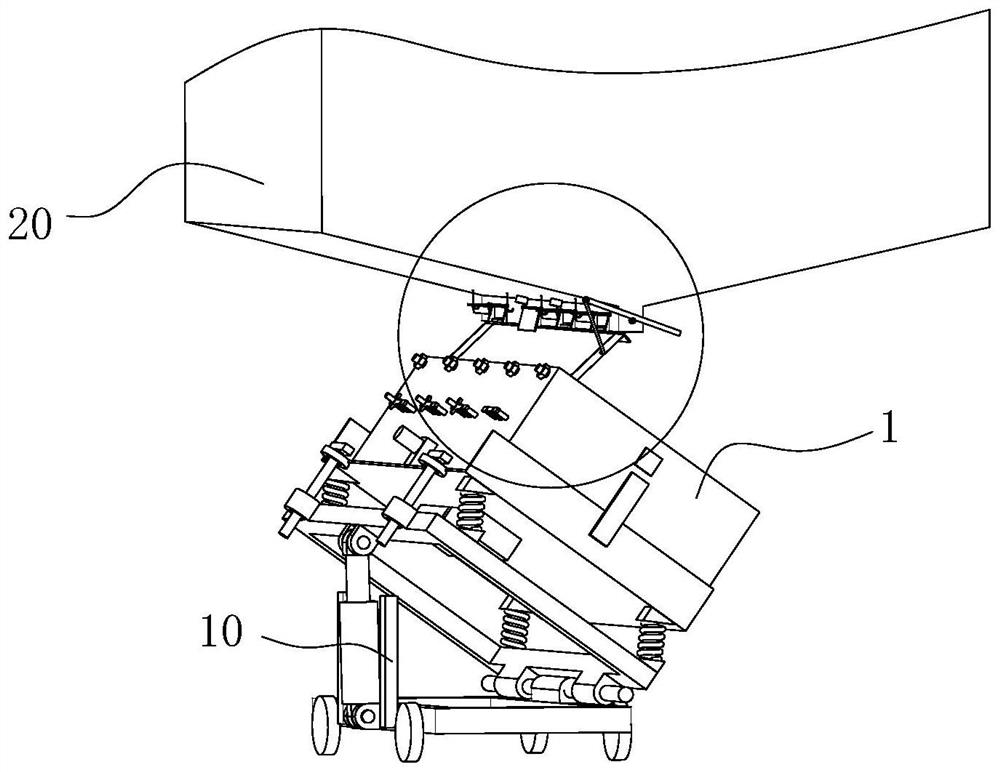
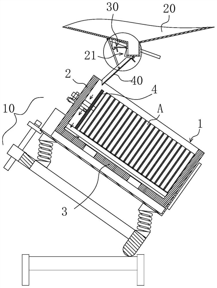
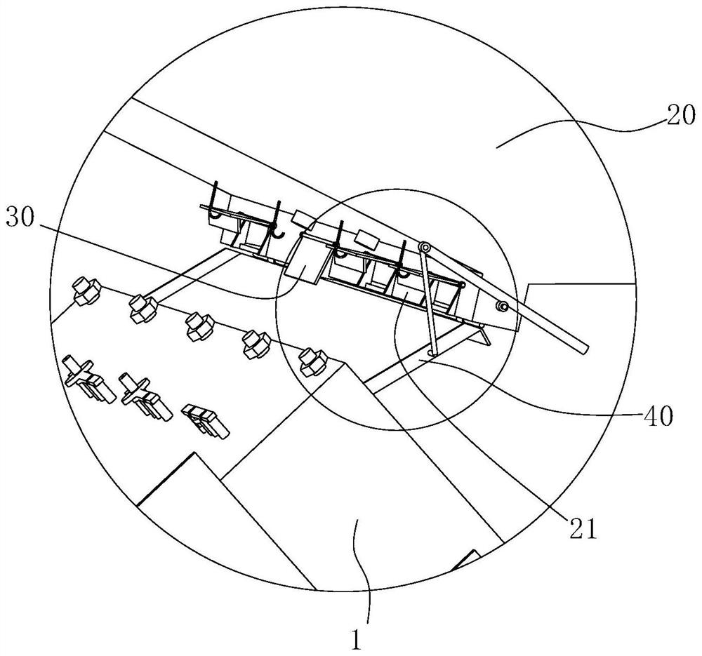
[0013] Such as figure 1 , 2 As shown, the bracket 10 will support the sand box 1 so that the bottom 3 of the box is in an inclined posture, which ensures that the cavity between the bottom 3 of the box and the bottom of the core type A of the coated sand shell presents an oblique posture, and the sand box For the structure, please refer to the patent document named "Sand Shell Core Casting Box" (document number CN 109226696A). At this time, the flow path of the outer molding sand flowing from the sand outlet 21 is limited to reach the inner side of the upper edge of the box wall 2 on the high side This part is also the space between the box wall 2 and the movable platen 4 that clamps the coated sand shell core type A set in the sand box 1. The falling sand enters from this place and moves along the box wall 2 and the movable platen 4. The clamp cavity between the pressing plates 4 falls to the high position of the box bottom 3, and then flows from the high position of the box...


PUM


Abstract

The invention provides a sand silo sand discharging device which is characterized in that a sand outlet is formed in the lower portion of a sand silo, an included angle is formed between the opening direction of the sand outlet and a plumb bob face, and a sand discharging valve is connected to the upper opening edge of the sand outlet through a horizontal hinge shaft. The sand discharging valve swings around the hinge shaft and can be in a closed sand discharging state of blocking the sand outlet area and an open sand discharging state of being far away from the sand outlet. According to the technical scheme, the opening direction of the sand outlet and the plumb bob face are arranged in an included angle mode, smooth flowing of sand flow is guaranteed, the sand flow is softer, appropriate flow can be obtained, in addition, due to the fact that the sand discharging valve is arranged in a swing mode, strict linear movement track limiting matching is not needed, the structure is obviously simplified, and the production cost is reduced. Particularly, the sand outlet is formed by the swinging action of the sand discharging valves, the sand discharging valves are matched efficiently, stably and reliably, and plugging and closing of the sand outlet are achieved.

Description

technical field [0001] The invention relates to a sand material storage and discharge device, specifically a sand bin sand discharge device. Background technique [0002] It is very common to use casting technology to process products. In casting processes such as sand casting, lost foam casting and coated sand casting, the mandrel mold shell containing the molding cavity is processed and placed in the sand box, and then implemented with ordinary external molding sand. Landfill, followed by casting and other processes. In order to improve the production efficiency, it is a conventional technique to store the ordinary external molding sand in the sand bin, transfer the sand box to the bottom of the sand outlet of the sand bin, and implement the ordinary external molding sand one by one for the sand box. [0003] In the patent document titled "A Sand Adding Device for a Core Shooting Machine" (document number CN104624984 A), the sand bucket 3 is installed on the frame 2 throu...

Claims


Application Information

Patent Timeline
Patent Type & Authority Applications(China)
IPC IPC(8): B22C5/12
CPCB22C5/12
Inventor 胡忠发胡适
Owner 黄山中发耐磨材料科技股份有限公司
Learn More