
Device and method for monitoring slow-speed and over-load rotor eccentricity image

A technology for rotor eccentricity and image monitoring, which is applied to measurement devices, optical devices, instruments, etc., can solve the problem of difficulty in giving the value of eccentricity, and achieve the effect of simple structure and convenient method.

Inactive Publication Date: 2009-10-14
XUZHOU UNIV OF TECH
View PDF0 Cites 23 Cited by
  • Summary
  • Abstract
  • Description
  • Claims
  • Application Information

AI Technical Summary

Problems solved by technology

Since the signals collected by the sensor often contain a large amount of noise and other interference signals, which have a great impact on the subsequent processing, it can only give a prompt or alarm when the eccentricity is large, and it is difficult to give a more accurate eccentricity value

Method used


Image

  • Device and method for monitoring slow-speed and over-load rotor eccentricity image
  • Device and method for monitoring slow-speed and over-load rotor eccentricity image
  • Device and method for monitoring slow-speed and over-load rotor eccentricity image

Examples


Embodiment Construction

[0018] The present invention will be further described below in conjunction with the example in the accompanying drawings:

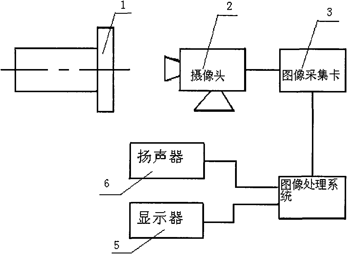
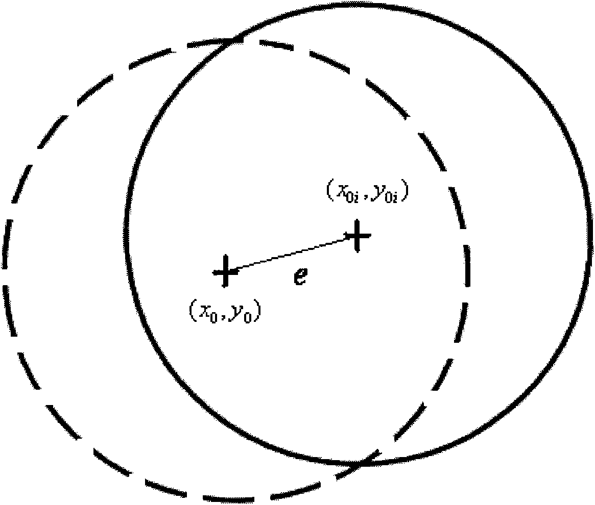
[0019] figure 1 As shown, the low-speed heavy-duty rotor eccentricity image monitoring device is mainly composed of a standard circular part 1, a high-resolution camera 2, an image acquisition card 3, an image processing system 4, a display 5 and a speaker 6. The standard circular part 1 is installed On the tested rotating shaft, the diameter of the standard circular piece 1 is about 50 mm, and the thickness is about 10 mm. The high-resolution camera 2 is arranged in the front of the section of the standard circular piece 1, and the resolution of the high-resolution camera 2 is more than 1280 pixels×800 pixels. The high-resolution camera 2 takes pictures of the standard circular piece 1 at the end of the rotary shaft. The high-resolution camera 2 is connected to the image acquisition card 3, and the image acquisition card 3 is connected to the image pro...


PUM

PropertyMeasurementUnit
Diameteraaaaaaaaaa
Thicknessaaaaaaaaaa

Abstract

The invention relates to a device and a method for monitoring slow-speed and over-load rotor eccentricity image. The device consists of a standard circular component, a high-resolution camera, an image capture card and an image processing system, wherein, the standard circular component is arranged on the revolving shaft of a rotor to be tested, and the image processing system outputs a processed result. The method comprises the following steps: the standard circular component is arranged at the revolving shaft of the rotor to be tested; the high-resolution camera is arranged in the right front of the sectional plane of the standard circular component; the high-resolution camera shoots the turning standard circular component; the image capture card captures image transmitted by the high-resolution camera; and the image processing system compares the image captured by the image capture card with the image of the built-in standard component without eccentric position and counts the eccentricity of the tested rotor and the maximal eccentricity during around-turning. The device is simple in structure, the method is convenient, and the eccentricity at different positions during the around-turning of the rotor can be monitored and counted.

Description

technical field [0001] The invention relates to a monitoring method and device, in particular to a low-speed heavy-duty rotor eccentricity image monitoring device and method suitable for low-speed rotors of less than 500 r / min for rotary motion. Background technique [0002] Rotary motion is the most common type of motion in mechanical equipment. Except for the special use of eccentric mechanisms to achieve centrifugal vibration such as vibrating pumps or to achieve certain motion conversion such as eccentric wheels, most of the rotary mechanisms are synchronized with the rotary hole and shaft. The axiality has higher requirements, mainly to limit the rotary vibration generated in the rotary motion within a certain range, otherwise the vibration will generate a lot of noise, and even have a destructive effect on mechanical equipment, especially at low speed and heavy load Excessive eccentric rotation of slewing equipment can cause serious damage and significant losses. The ...

Claims


Application Information

Patent Timeline
IPC IPC(8): G01B11/27
Inventor 陈跃张建化张宏艳朱雷平张清
Owner XUZHOU UNIV OF TECH
Learn More