Adjustable patch photonic crystal micro-stripe antenna

A technology of photonic crystals and microstrip antennas, applied in antennas, electrical components, etc., can solve the problems of increased back lobe fluctuations, reduced antenna efficiency, and enlarged, etc.

Inactive Publication Date: 2009-10-14
UNIV OF ELECTRONICS SCI & TECH OF CHINA
View PDF0 Cites 4 Cited by
  • Summary
  • Abstract
  • Description
  • Claims
  • Application Information

AI Technical Summary

Problems solved by technology

[0010] The existence of surface waves in the microstrip antenna, on the one hand, makes the energy "bound" near the medium and cannot radiate, which reduces the efficiency of the antenna, which can be reduced to only a few tens of percent; on the other hand, radiation and winding occur at the cut-off of the medium Radiation affects the antenna pattern, mainly due to the increase of the back lobe and the increase of the fluctuation of the side lobe
[0011] Studies have shown that when the surface wave power in the antenna is very high, the efficiency of the antenna will become very low, and the space-time wave radiation efficiency η s maybe only 30% or even lower

Method used


Image

  • Adjustable patch photonic crystal micro-stripe antenna
  • Adjustable patch photonic crystal micro-stripe antenna
  • Adjustable patch photonic crystal micro-stripe antenna

Examples


Embodiment Construction

[0025] The present invention will be further described below in conjunction with accompanying drawing:

[0026] The adjustable patch photonic crystal microstrip antenna includes an FR4 substrate, a TPEE light soft rubber layer, two compatible electrodes, a hollow cylindrical scatterer made of dielectric elastic material and a patch microstrip antenna.

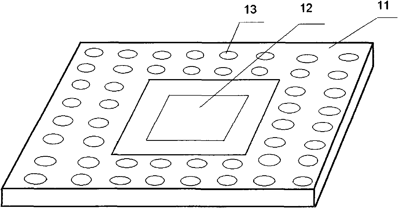
[0027] Such as figure 1 As shown, the FR4 substrate 11 is surrounded by photonic crystals of several periods (usually 3 to 5 periods), and the middle of the substrate is a patch microstrip antenna 12; There is a certain distance between them (usually 1 to 2 photonic crystal periods).

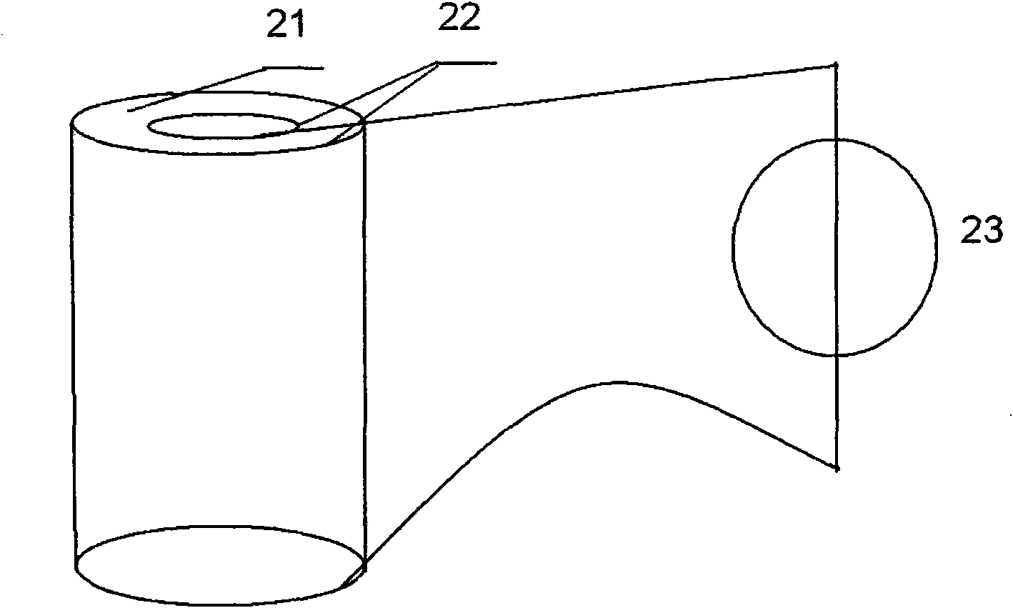
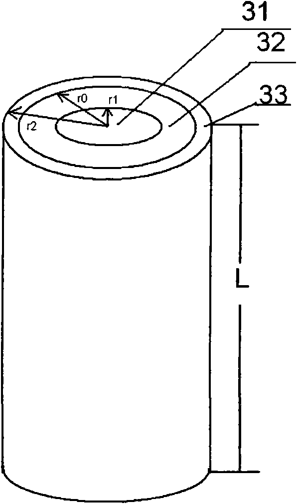
[0028] Such as figure 2 , image 3 As shown, the hollow cylinder scatterer 13 of the scatterer unit 13 is a hollow cylinder made of a dielectric elastic material, the inner and outer surfaces are plated with compatible electrodes 22 and connected to an adjustable voltage source 23, and a light soft rubber layer 33 is provided on the extension...


PUM


Abstract

The invention discloses an adjustable patch photonic crystal micro-stripe antenna which comprises an RF4 substrate. The RF4 substrate is provided with a patch micro-stripe antenna in the middle; four sides of the patch micro-stripe antenna is provided with photonic crystals of a plurality of cycles; intervals of 1-2 photonic crystal cycles are provided between the photonic crystals and the patch micro-stripe antenna; scatterer units of the photonic crystals are hollow columnar scatterers; the hollow columnar scatterers are hollow columns prepared by dielectric elastic materials; inner and outer surfaces of the hollow columns are provided with compatible electrodes which are connected to an adjustable voltage source; a light flexible glue layer is provided on outer margin, thereby changing thicknesses of the hollow columnar scatterers by the adjustable voltage source to cause shifts of forbidden region frequencies of the photonic crystal, to inhibit surface waves of various frequencies; therefore, various operating frequencies of the micro-stripe antenna can be generated by coupling effect.

Description

technical field [0001] The invention relates to a microstrip antenna, in particular to an adjustable photonic crystal microstrip antenna. Background technique [0002] Microstrip antenna is a new type of antenna developed gradually in the past 30 years. As early as 1953, the concept of microstrip antenna was proposed, but it did not attract the attention of the engineering community. There were only a few sporadic studies in the 1950s and 1960s, and the real development and use came in the 1970s. A commonly used type of microstrip antenna is on a thin dielectric substrate (such as polytetrafluoroethylene glass fiber laminate), with a thin metal layer attached on one side as a grounding plate, and a metal paste of a certain shape is made on the other side by photolithography and other methods. The patch is fed with a microstrip line and an axis probe, which constitutes a microstrip antenna. When the patch is an area unit, it is called a microstrip antenna; if the patch is ...

Claims


Application Information

Patent Timeline
Patent Type & Authority Applications(China)
IPC IPC(8): H01Q13/08
Inventor 杨立峰王亚非万勇高椿明周鹰王占平
Owner UNIV OF ELECTRONICS SCI & TECH OF CHINA
Why Eureka
Try Eureka