

Frequency-selective broadband waveguide slot antenna array
A frequency selective, slot antenna technology, applied in slot antennas, antenna arrays, antennas, etc., can solve problems such as poor anti-interference ability, and achieve the effects of weight reduction, interference suppression, and large loss
- Summary
- Abstract
- Description
- Claims
- Application Information
AI Technical Summary
Problems solved by technology
Method used
Image

Examples
Embodiment 1
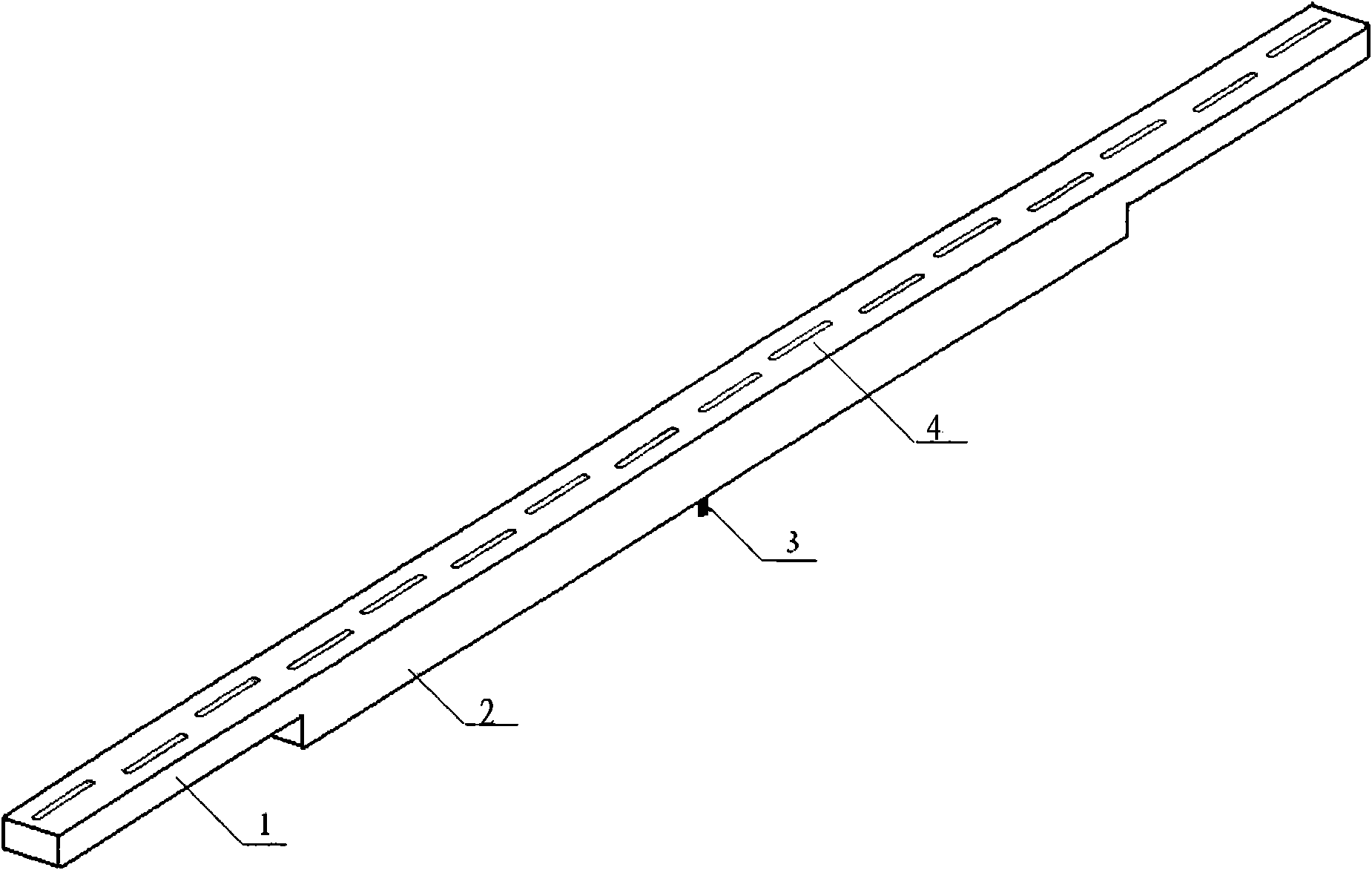
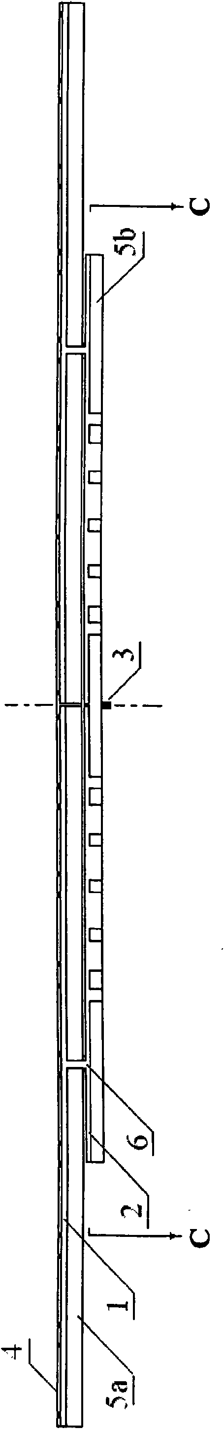
[0031] see figure 1 , image 3 , Figure 5 and Figure 6 , a preferred embodiment is a uniformly distributed 16-element waveguide slot antenna array (five-stage filter antenna) working in the X-band, and the antenna operating frequency range is f L ~ f H , where f L is the lowest frequency, f H is the highest frequency, f 0 is the center frequency, and the upper side frequency of the stop band is f S .
[0032] The antenna array consists of radiation waveguide 1, feed waveguide 2, coaxial connector 3 and radiation slot 4, such as figure 1 shown.
[0033] The radiation waveguide 1 is a rectangular metal ridge waveguide with internal ridges, the terminal is closed, and the metal ridge 5a is located on the center line of the bottom edge, such as image 3 and 6 shown.
[0034] The feeding waveguide 2 is also a rectangular metal ridge waveguide with a closed terminal and internal ridges. The metal ridge 5b is located on the center line of the bottom edge, as shown in ...
Embodiment 2
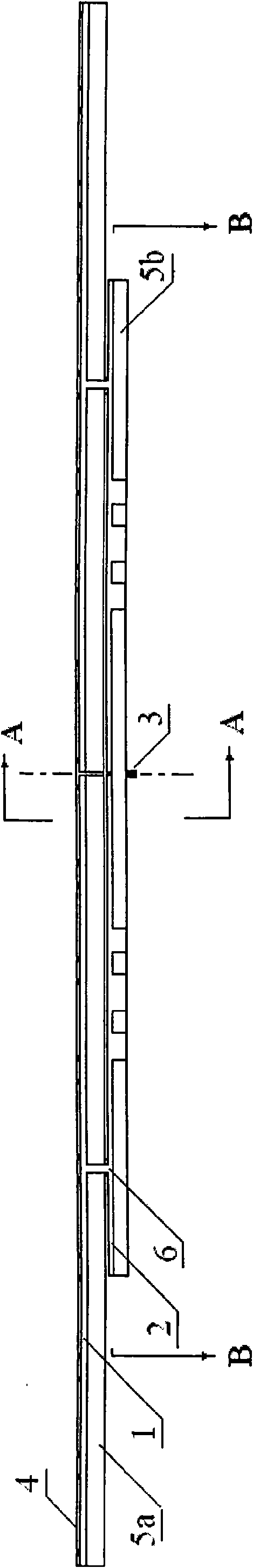
[0049] see figure 2 , Figure 4 and Figure 6 , working in the X-band, uniformly distributed 16-element waveguide slot antenna array (secondary filter antenna), on the metal ridge 5b of the feeding waveguide 2, between the coaxial connector 3 and the coupling slots 6 on both sides, each with 3 grooves, such as figure 2 and 4 As shown, there are 2 short metal ridges between the phases, that is, a 2-stage filter. In this embodiment, the filter size and position parameters are preferably: L1=0.171λ 0 , L2=0.252λ 0 , W0=1.74λ 0 , W1=0.168λ 0 .
[0050] Others are with embodiment 1.
PUM
 Abstract
Description
Claims
Application Information