

Antiglare film, process for producing the same and display apparatus utilizing the film
An anti-glare film and anti-glare layer technology, applied in chemical instruments and methods, transportation and packaging, instruments, etc., can solve problems such as deterioration of anti-glare properties, and achieve suppression of white turbidity, reduction of protrusions, and improvement of surface roughness. Effect
- Summary
- Abstract
- Description
- Claims
- Application Information
AI Technical Summary
Problems solved by technology
Method used
Image

Examples
no. 1 approach
[0101] (1-1) Structure of liquid crystal display device
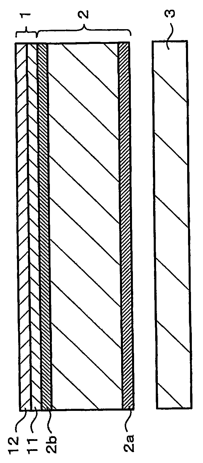
[0102] figure 1 An example of the configuration of the liquid crystal display device according to the first embodiment of the present invention is shown. Such as figure 1 As shown, the liquid crystal display device has a liquid crystal panel 2 and a light source 3 arranged directly below the liquid crystal panel 2. The liquid crystal panel 2 has an anti-glare film 1 on its display screen side.
[0103] The light source 3 is used to provide light to the liquid crystal panel 4, and has, for example, a fluorescent lamp (FL), EL (electroluminescence), LED (light emitting diode), and the like. The liquid crystal panel 2 is used to temporally and spatially adjust the light provided by the light source 3 and display information. Polarizing plates 2a and 2b are provided on both surfaces of the liquid crystal panel 2. Each of the polarizing plates 2a and 2b allows only one of the perpendicularly crossing polarized light component...
no. 2 approach
[0157] (2-1) Structure of anti-glare film
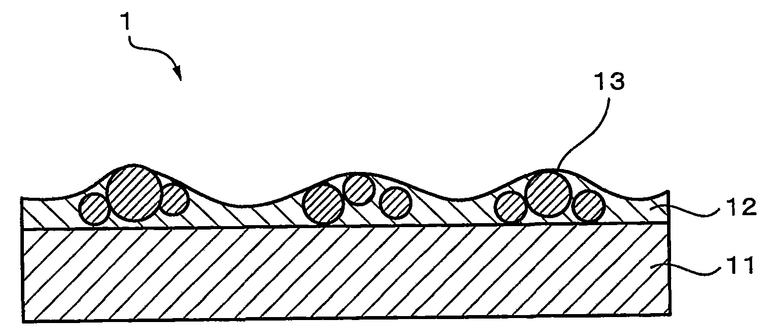
[0158] Figure 4 An example of the configuration of the anti-glare film 10 according to the second embodiment of the present invention is shown. In the anti-glare film 10, an anti-glare layer 12 containing fine particles 13 is formed on a substrate 11, and a transparent resin layer 14 having light transmittance is formed on the anti-glare layer 12. The base material 11, the anti-glare layer 12, and the fine particles 13 are similar to those in the first embodiment described above. On the surface of the anti-glare layer 12, a fine concavo-convex shape formed by convection and aggregation of fine particles 13 is formed.
[0159] The transparent resin layer 14 is laminated on the anti-glare layer 12, which is a layer whose refractive index is lower than that of the anti-glare layer 12, and can reduce the reflectance of the surface. The transparent resin layer 14 is formed along the anti-glare layer 12, for example, and covers the surface of...
Embodiment 1
[0184] First, as fine particles, crosslinkable styrene pellets SBX6 (manufactured by SEKISUI PLASTICS CO., LTD.) having a center particle size equal to about 6 μm are separated by fine powder. The classification is carried out by the mechanical method, and fine particles of 10 μm or more are removed. The average diameter of the fine particles obtained after the classification process is equal to 6.3 μm, the median diameter is equal to 5.5 μm, and the fluctuation coefficient is equal to 31%.
[0185] Next, by using the fine particles obtained after the classification process, the raw materials of the following coating composition are mixed. The paint was stirred with a magnetic stirrer for one hour, and filtered through a 20 μm sieve with a roughness equal to or greater than three times the average diameter. After that, one surface of a triacetyl cellulose (TAC) film (manufactured by Fuji Photo Film Co., Ltd.) having a thickness of 80 μm (manufactured by Fuji Photo Film Co., Ltd.) ...
PUM
| Property | Measurement | Unit |
|---|---|---|
| thickness | aaaaa | aaaaa |
| thickness | aaaaa | aaaaa |
| diameter | aaaaa | aaaaa |
Abstract
Description
Claims
Application Information