Variable compression ratio device of automobile engine

An automotive engine and compression ratio technology, which is applied in engine control, machine/engine, mechanical equipment, etc., can solve the problems of large changes to the engine, complex mechanical structure, and low development cost of variable compression ratio engines, achieving light weight, Low cost and low motion inertia

Inactive Publication Date: 2009-10-21
张志强
View PDF0 Cites 26 Cited by
  • Summary
  • Abstract
  • Description
  • Claims
  • Application Information

AI Technical Summary

Problems solved by technology

[0003] The purpose of the present invention is to solve the shortcomings of the variable compression ratio engine, such as large changes to the engine, complicated mechanical structure, high cost, and low reliability, and provide a method that does not change the cylinder head, cylinder, piston, main connecting rod, etc. of the current mature engine. Under the premise of crankshaft and cranks

Method used


Image

  • Variable compression ratio device of automobile engine
  • Variable compression ratio device of automobile engine

Examples


Embodiment 1

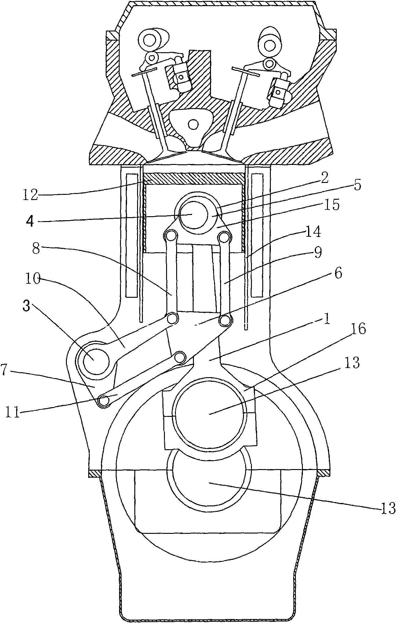
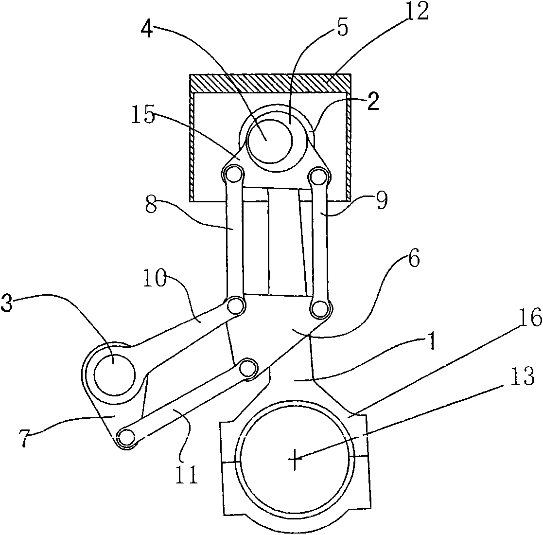
[0015] Such as figure 1 , figure 2 As shown, the main connecting rod 1 of the engine is connected to the crankshaft 13, the piston 12 in the cylinder 14 is connected to the small head 2 of the main connecting rod through the piston pin 4, and an eccentric bushing is arranged between the piston pin 4 and the small head 2 of the main connecting rod The sleeve 5 and the eccentric bushing 5 are fixedly connected with two ear arms 15, and the two ear arms 15 are respectively hinged with the first connecting rod 8 and the second connecting rod 9, and the first connecting rod 8 and the second connecting rod 9 are respectively connected with the replacement The reversing frame 6 is hinged with the third link 10 and the fourth link 11 respectively, and the third link 10 is hinged with the adjustment shaft 3, and the fourth link 11 is hinged with the drive arm 7 connected to the adjustment shaft 3, thereby forming a second parallelogram hinge four-bar mechanism; the drive arm 7 is con...

Embodiment 2

[0017] The eccentric bushing 5 is arranged between the main journal of the crankshaft 13 and the main bearing seat hole of the crankcase, and the others are the same as in the first embodiment.

Embodiment 3

[0019] The eccentric bushing 5 is arranged between the big end 16 of the main connecting rod and the connecting pin of the crankshaft 13, and the others are the same as in the first embodiment.


PUM


Abstract

The invention discloses a variable compression ratio device of an automobile engine, comprising a crank shaft, a main connecting rod, a piston, an eccentric sleeve, a hinge bar transmission mechanism and a regulating shaft; a small end of the main connecting rod is connected with the piston by a piston pin, and a large end thereof is connected with the crank shaft; the eccentric sleeve is arranged between the small end of the main connecting rod and the piston pin, a connecting rod neck and the large end of the main connecting rod, or a main journal of the crank shaft and a main bearing saddle bore of a crank shaft case; the hinge bar transmission mechanism is used for the transmission between the regulating shaft and the eccentric sleeve. The hinge bar transmission mechanism controls the rotation of the eccentric sleeve, and can change the position of a dead point on the piston so as to change the compression ratio of the engine; furthermore, the hinge bar transmission mechanism is formed by two parallelogrammic hinged four-bar linkage mechanisms, so that the variable compression ratio device has the advantages of simple structure, easy fabrication, convenient control, reliable use, durability and low cost.

Description

technical field [0001] The invention relates to the technical field of automobile engines, in particular to a variable compression ratio device for automobile engines. Background technique [0002] Swedish SAAB (Shenbao) company first applied variable compression ratio technology to automobile engines. This technology can significantly improve the power performance of the engine, reduce fuel consumption and emissions, and increase the power per liter, which is conducive to engine miniaturization, especially in terms of energy saving and emission reduction. It has obvious advantages and is one of the core technologies of the next-generation automobile engine. At present, there are many variable compression ratio technical solutions. Although the effect of this technology on energy saving and emission reduction is very obvious, most of the variable compression ratio solutions further complicate the mechanical structure of the engine, greatly increase the cost, and reduce the r...

Claims


Application Information

Patent Timeline
IPC IPC(8): F02B75/32F02D15/02
CPCF02B75/045
Inventor 张志强
Owner 张志强
Why Eureka
Try Eureka