
Novel pipeline support structure applied to high-speed geotechnical centrifugal machine

A geotechnical centrifuge and support structure technology, which is applied in the direction of centrifuge, pipe support, pipe protection, etc., can solve the problems of inconvenient operation, difficult installation, and affecting the dynamic balance of the rotating arm, so as to achieve easy maintenance and replacement, simple installation and disassembly, The effect of reducing replacement costs

Pending Publication Date: 2022-01-18
GENERAL ENG RES INST CHINA ACAD OF ENG PHYSICS
View PDF0 Cites 0 Cited by
  • Summary
  • Abstract
  • Description
  • Claims
  • Application Information

AI Technical Summary

Problems solved by technology

However, the arrangement of existing pipes and cables makes them protrude from the upper surface of the rotating arm, which destroys the good aerodynamic shape of the rotating arm and increases the wind resistance of the centrifuge operation
[0009] 2. Weak protection ability
When the centrifuge acceleration of the high-speed geotechnical centrifuge reaches 1000g, the traditional pipeline installation structure will not be able to provide enough friction to balance the centrifugal force on the pipeline, so the cable will break under the action of centrifugal force, which cannot meet the power supply requirements of the high-speed geotechnical centrifuge
[0011] 3. Affect the structural strength and dynamic balance of the boom
Drilling holes to arrange pipes and cables on the boom will easily lead to uneven mass distribution, which will affect the dynamic balance of the boom
[0014] Therefore, traditional pipe and cable fixing methods cannot be applied to high-speed geotechnical centrifuges
[0015] 4. Difficult installation and low troubleshooting efficiency
[0016] The traditional pipeline support method needs to arrange a large number of pipe clamps and wire clamps on the rotating arm of the geocentrifuge. This work requires the dismantling of the rotating arm of the geocentrifuge or personnel climbing to the rotating arm of the geocentrifuge for operation. The height of the working surface High, inconvenient to operate
If the cable is faulty, it is necessary to disassemble the cable and find out the faulty cable before bundling and fixing it. The troubleshooting efficiency is low.

Method used


Image

  • Novel pipeline support structure applied to high-speed geotechnical centrifugal machine
  • Novel pipeline support structure applied to high-speed geotechnical centrifugal machine
  • Novel pipeline support structure applied to high-speed geotechnical centrifugal machine

Examples


Embodiment Construction

[0042] In order to make the object, technical solution and advantages of the present invention more clear, the present invention will be further described in detail below in conjunction with the accompanying drawings and embodiments. It should be understood that the specific embodiments described here are only used to explain the present invention, and are not intended to limit the present invention, that is, the described embodiments are only some of the embodiments of the present invention, but not all of the embodiments. The components of the embodiments of the invention generally described and illustrated in the figures herein may be arranged and designed in a variety of different configurations.

[0043] Accordingly, the following detailed description of the embodiments of the invention provided in the accompanying drawings is not intended to limit the scope of the claimed invention, but merely represents selected embodiments of the invention. Based on the embodiments of ...


PUM


Abstract

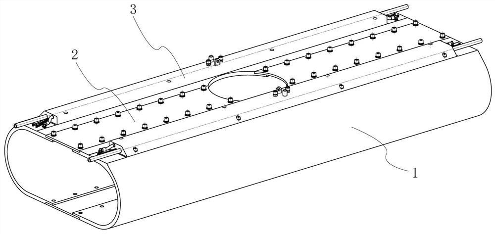
The invention relates to the technical field of geotechnical centrifugal machines, and particularly discloses a novel pipeline support structure applied to a high-speed geotechnical centrifugal machine, the novel pipeline support structure comprises two side supports and four connecting plates, wherein the two side supports are oppositely and symmetrically arranged and are connected through the four connecting plates, each side support is of a U-shaped structure; every two of the four connecting plates are grouped to be connected with the upper sides and the lower sides of the two side supports respectively, a mounting gap is formed between the two connecting plates in the same group, and preset parts are arranged at the tops of the two side supports. The invention has the advantages that a pipeline, a strong-current cable and a weak-current cable are all pre-embedded in the preset part made of the high-strength fibers, and the pipeline and the cable are protected by the high-strength fibers to meet the water supply and power supply requirements of the high-speed geotechnical centrifugal machine, so that protrusions on the outer surface of the rotary arm of the geotechnical centrifugal machine are reduced; the outer surfaces of the side supports of a pipeline mounting structure are cured and formed through a mold, so that smooth transition of the outer surface can be achieved, and therefore, the wind resistance of the geotechnical centrifugal machine is reduced.

Description

technical field [0001] The invention relates to the technical field of geotechnical centrifuges, in particular to a novel pipeline support structure applied to high-speed geotechnical centrifuges. Background technique [0002] Geotechnical centrifuge is an experimental device used in geotechnical engineering and other fields. It can simulate the supergravity field by using the stable centrifugal acceleration field formed by high-speed rotation. According to the similarity ratio principle of the model, researchers can conduct experimental research on real-world 100-meter-high dams and giant landslides on geotechnical centrifuges to evaluate their safety and grasp the mechanism of landslides. In addition, geotechnical centrifuges are also widely used in deep sea engineering, underground environmental pollutant assessment, earthquake resistance assessment of urban building structures, high-energy explosion research and other fields. The field provides strong support. [0003]...

Claims


Application Information

Patent Timeline
Patent Type & Authority Applications(China)
IPC IPC(8): B04B15/00G01N33/24F16L3/10F16L3/202F16L57/02H02G3/04
CPCB04B15/00G01N33/24F16L3/1066F16L3/202F16L57/02H02G3/0487H02G3/0406
Inventor 陈良军李心耀宋琼冉光斌郑殿臣张志强沈展鹏
Owner GENERAL ENG RES INST CHINA ACAD OF ENG PHYSICS
Learn More