
Runner used for direct connection low-speed small-scale mixed-flow turbine of hydrodynamic energy-saving cooling tower

An energy-saving, cooling tower technology, applied in the field of cooling towers, can solve the problems of easy failure, manufacturing cost, high noise, etc., and achieve the effect of simple structure, convenient installation and use

Inactive Publication Date: 2009-10-21
NANJING XINGFEI COOLING EQUIP
View PDF0 Cites 10 Cited by
  • Summary
  • Abstract
  • Description
  • Claims
  • Application Information

AI Technical Summary

Problems solved by technology

[0004] The purpose of the present invention is to design a hydrodynamic energy-saving cooling tower for the problems that the output shaft of the existing cooling tower water turbine needs to pass through the reduction box to drive the fan blades, resulting in high noise, easy failure and high manufacturing cost. Directly connected to the runner of the low-speed small Francis turbine, thus laying the foundation for the final elimination of the gear reduction transmission mechanism

Method used


Image

  • Runner used for direct connection low-speed small-scale mixed-flow turbine of hydrodynamic energy-saving cooling tower
  • Runner used for direct connection low-speed small-scale mixed-flow turbine of hydrodynamic energy-saving cooling tower
  • Runner used for direct connection low-speed small-scale mixed-flow turbine of hydrodynamic energy-saving cooling tower

Examples


example 1

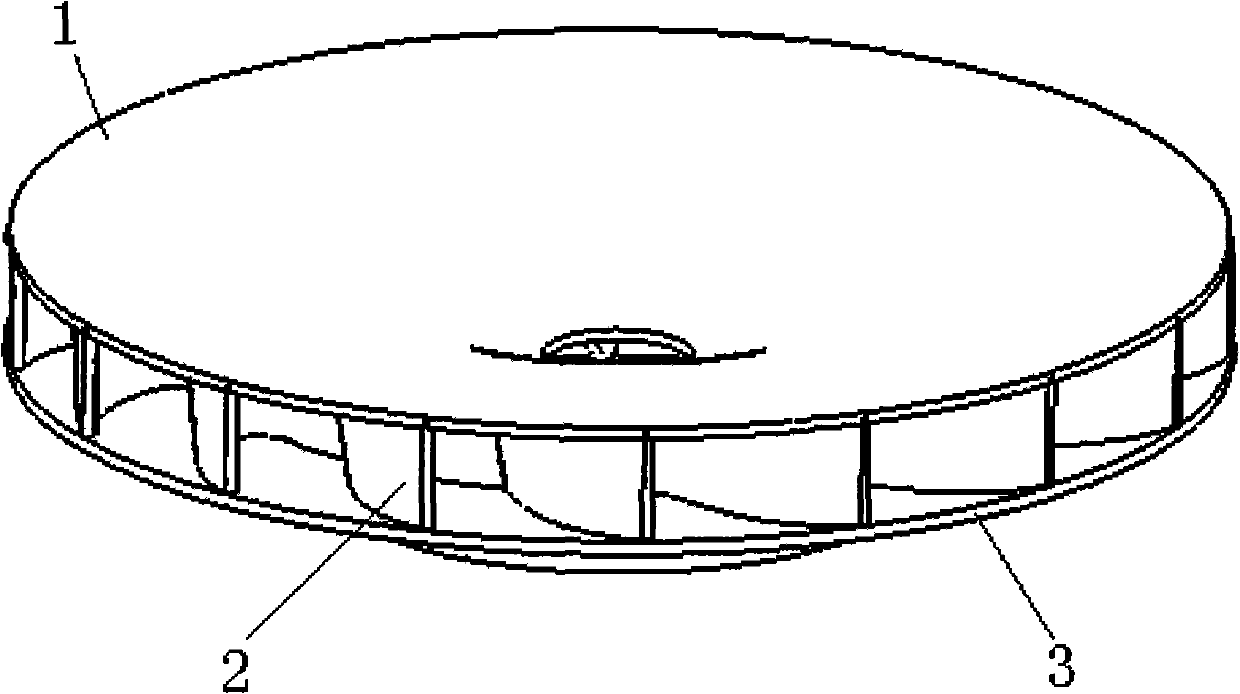
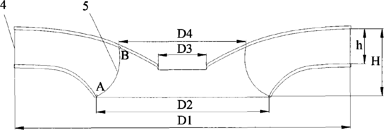
[0023] Let n11 be 35, the water pressure H entering the tower is 13m, the rated speed n of the fan blade is 136r / min, and D1 is 0.928m, and the shape of a curved blade is designed as image 3 , 4 shown. Installed and measured fan blade speed is 137r / min, in line with the design requirements.

example 2

[0025] Let n11 be 30, the water pressure H entering the tower is 15m, the rated speed n of the fan blade is 140r / min, and D1 is 0.830m, and the shape of a curved blade is designed as image 3 , 4 shown. The speed of installed and measured fan blades is 138r / min, which meets the design requirements.

example 3

[0027] Let n11 be 40, the water pressure H entering the tower is 15m, the rated speed n of the fan blade is 130r / min, and D1 is 1.192m, and the shape of a curved blade is designed as image 3 , 4 shown. Installed and measured fan blade speed is 131r / min, in line with the design requirements.


PUM


Abstract

A runner used for a direct connection low-speed small-scale mixed-flow turbine of a hydrodynamic energy-saving cooling tower, comprising an upper canopy (1), a runner band (3) and a curved vane (2) arranged between the upper canopy (1) and the runner band (3). The runner is characterized in that the ratio between the height h of a leading edge (4) of the vane (2) and the diameter D1 corresponding to the leading edge (4) is 0.18-0.22; the ratio between the total height H of the vane (2) and the diameter D1 is 0.35-0.42; the ratio between the diameter D2 and the diameter D1 is 0.4-0.6 and wherein the diameter D2 corresponds to the intersection A of the leading edge (4) and runner band (3); the ratio between the diameter D3 and the diameter D1 is 0.3-0.45, wherein the diameter D3 corresponds to the intersection B of the leading edge (4) and the upper canopy; the ratio between the diameter D4 of a draining round platform at the upper canopy (1) and the diameter D1 is 0.1-0.2, the relation between the diameter D1 and the rotating speed of a cooling fan blade is D1=n11*square root of H / n. The invention has the advantages of simple structure, convenient design and installation and high energy conversion efficiency.

Description

technical field [0001] The invention relates to a cooling tower, in particular to a cooling tower driving a runner of a water turbine, specifically a cooling tower without a reduction box. By rationally designing the runner of the water turbine, the output speed of the water turbine is equal to the rated value of the fan speed, thereby saving The runner used for the direct-connected low-speed small Francis turbine of the hydrodynamic energy-saving cooling tower without the reduction box used by the traditional reaction turbine. Background technique [0002] As we all know, in order to achieve the purpose of energy saving, the existing air-conditioning cooling towers have begun to use water turbines to drive the cooling fans. It makes full use of the energy of the cooling tower circulating water flow and converts it into the driving force of the water turbine. The rotating mechanical energy is used to drive the cooling fan, which saves the traditional high-power cooling motor...

Claims


Application Information

Patent Timeline
IPC IPC(8): F03B3/12F03B13/00
CPCF03B3/121F01D5/02Y02E10/28F03B3/125Y02E10/223F05B2250/71Y02E10/20F03B3/12F03B17/06
Inventor 顾星康
Owner NANJING XINGFEI COOLING EQUIP
Learn More