
Phase controllable multi-frequency fiber interference fringe projection device

A technology of optical fiber interference and projection device, applied in the direction of coupling of optical devices, measuring devices, optical waveguides, etc., can solve the problems of not being able to guarantee the speed and accuracy of measurement at the same time, easily affecting the surface topography of the object to be measured, etc. Conducive to miniaturization and integration, ease of construction, and reduced interference

Inactive Publication Date: 2009-10-21
TIANJIN UNIV
View PDF0 Cites 15 Cited by
  • Summary
  • Abstract
  • Description
  • Claims
  • Application Information

AI Technical Summary

Problems solved by technology

Contact measurement is easy to affect the surface morphology of the measured object, and cannot guarantee the speed and accuracy of measurement at the same time

Method used


Image

  • Phase controllable multi-frequency fiber interference fringe projection device
  • Phase controllable multi-frequency fiber interference fringe projection device
  • Phase controllable multi-frequency fiber interference fringe projection device

Examples


Embodiment Construction

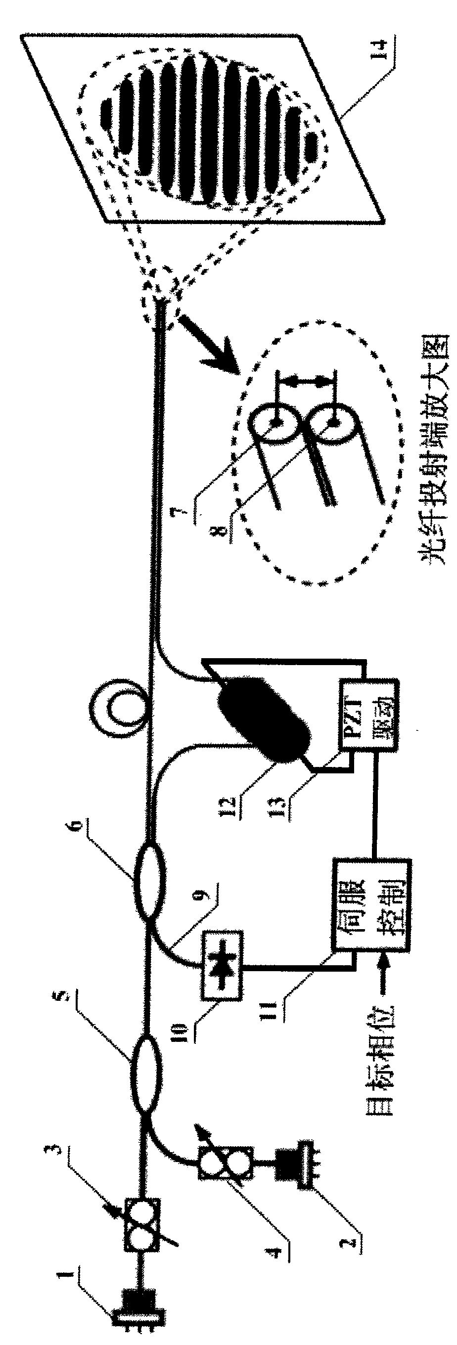
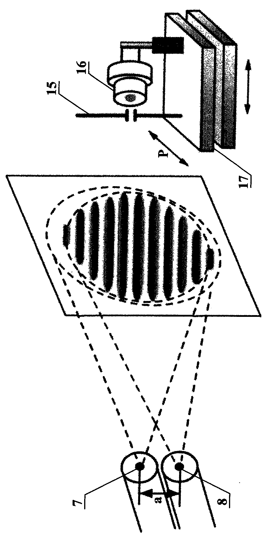
[0021] In order to increase the density of projected fringes, the present invention utilizes optical fiber interference projection technology, and adopts a 3dB single-mode optical fiber coupler to form a Mach-Zehnder interferometer. The incident light is split by the coupler and then output from two output ports, satisfying Young's two-hole interference condition , resulting in interference fringes on the projection side. Compared with the traditional transmission grating, the interference fringe density is higher, which is beneficial to improve the measurement accuracy.

[0022] A wavelength division multiplexer (WDM) is introduced at the incident end of the 3dB coupler. The lasers emitted by different frequency lasers are coupled into the input end of the same 3dB coupler through the WDM. The incident light is split by the coupler to generate multi-frequency interference fringes at the output side. . The projected multi-frequency interference fringes can provide multi-frequ...


PUM


Abstract

The invention relates to the technology of multi-frequency fiber interference fringes and three-dimensional topography measurement, in particular to a phase controllable multi-frequency fiber interference fringe projection device. In order to provide the phase controllable multi-frequency fiber interference fringe projection device with high measurement precision, stability and reliability, the invention adopts the technical proposal that: the device comprises a Mach-Zehnder interferometer forming the projection of an emergence end 7 and an emergence end 8, and also comprises a Michelson interferometer; an interference signal generated by the Michelson interferometer is transmitted to a photoelectric detector 10 through a non-incident end of a single-mode fiber coupler 6; the photoelectric detector 10 converts an optical signal into an electric signal and transmits the electric signal to a servo system 11; and the servo system 11 is used for controlling a piezoelectric ceramics PZT driving device 13 by comparing an actual phase and a target phase to drive a fiber stretcher 12 to change the optical path difference of two output arms of the single-mode fiber coupler 6. The device is mainly applied in three-dimensional topography measurement occasions.

Description

technical field [0001] The invention relates to multi-frequency optical fiber interference fringe and three-dimensional shape measurement technology, in particular to a phase-controllable multi-frequency optical fiber interference fringe projection device. Background technique [0002] Three-dimensional shape measurement technology occupies an important position in the fields of automatic detection and quality control, reverse engineering, machine vision, medical diagnosis, cultural relic identification, etc., especially in the processing and manufacturing of automobile bodies, aircraft fuselages, ship hulls, and steam turbine blades. The on-line surface detection has put forward higher requirements for the three-dimensional shape measurement technology, and promoted its development in the direction of high-precision and intelligent dynamic measurement. Three-dimensional shape measurement technology can be divided into two categories: contact and non-contact. Contact measur...

Claims


Application Information

Patent Timeline
IPC IPC(8): G01B11/25G02B6/42
Inventor 段发阶肖海张聪杨涛
Owner TIANJIN UNIV
Learn More