Magnetic-field-enhanced permanent-magnetic switching flux linkage motor with high fault tolerance

A permanent magnet switch and fault-tolerant technology, which is applied to synchronous motors with rotating armatures and stationary magnets, electrical components, electromechanical devices, etc. Interference and other problems, to achieve the effect of improving anti-electromagnetic interference and electromagnetic compatibility, increasing the amount of change, and outputting high power density

Inactive Publication Date: 2009-10-21
ZHEJIANG UNIV
View PDF0 Cites 10 Cited by
  • Summary
  • Abstract
  • Description
  • Claims
  • Application Information

AI Technical Summary

Problems solved by technology

However, the traditional fault-tolerant permanent magnet switch flux linkage motor has serious radial end flux leakage.
On the one hand, magnetic flux leakage leads to low utilization rate of permanent magnets, on the other hand, it also leads to problems of electromagnetic interference and electromagnetic compatibility, and at the same time, it also limits the use of non-magnetic materials for the motor casing.

Method used


Image

  • Magnetic-field-enhanced permanent-magnetic switching flux linkage motor with high fault tolerance
  • Magnetic-field-enhanced permanent-magnetic switching flux linkage motor with high fault tolerance

Examples


Embodiment Construction

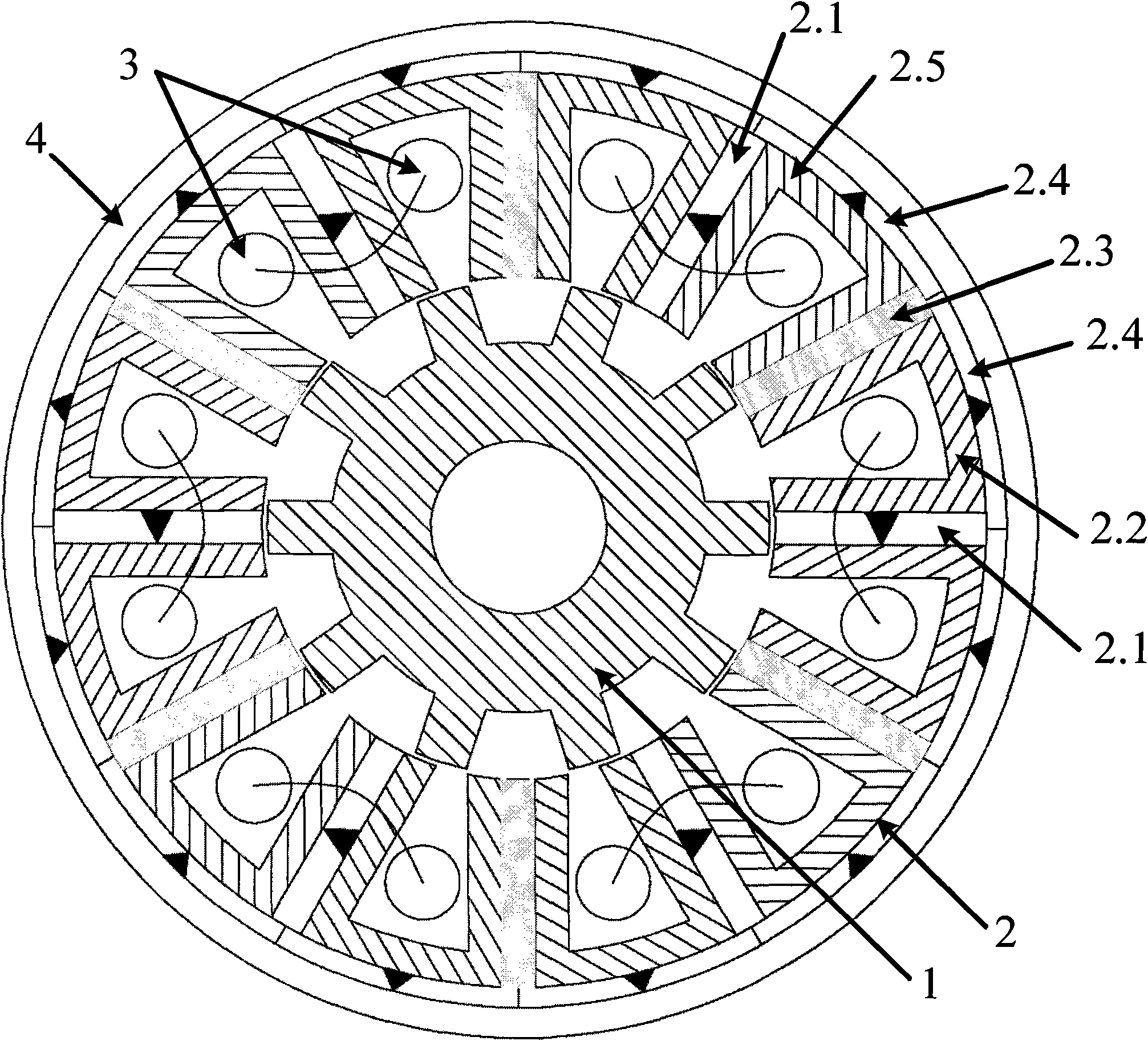
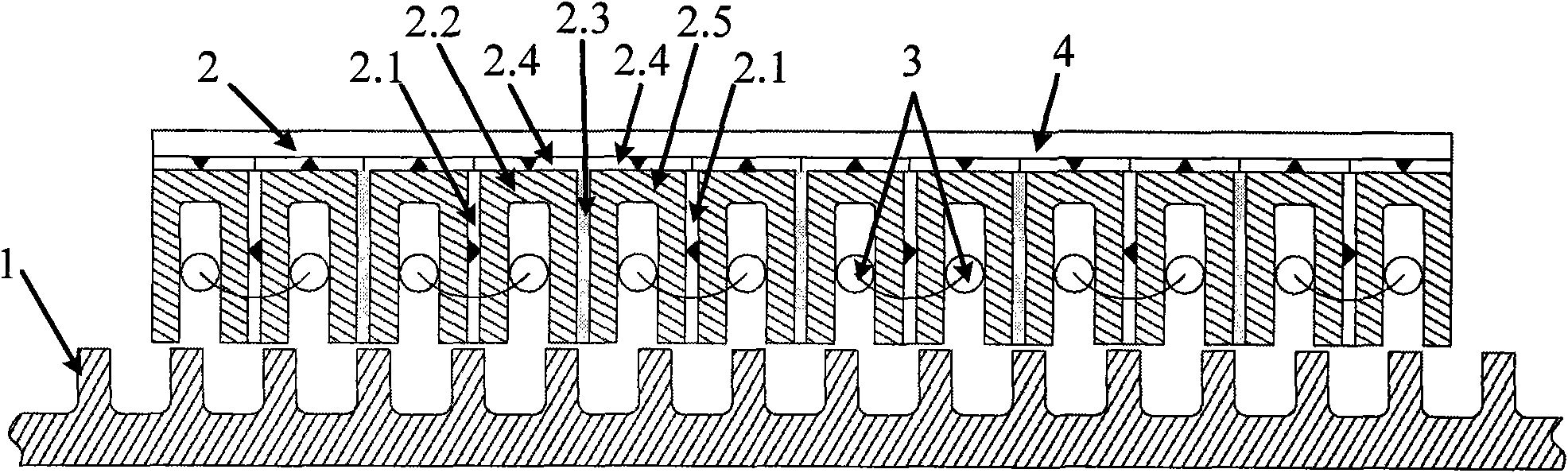
[0014] figure 1 It is a structure of a rotary high fault-tolerant magnetic field enhanced permanent magnet switch flux linkage motor, including a rotor 1, a stator 2, a three-phase armature winding 3 and a casing 4. The stator fixed in the casing includes the first permanent magnet 2.1, the first "U"-shaped iron core 2.2, the reluctance sheet 2.3 and the second "U"-shaped iron core 2.5 arranged in sequence, and the first "U"-shaped iron core The structure is the same as that of the second "U"-shaped iron core. The first permanent magnet is magnetized tangentially along the circumference. The "U" shaped iron core is formed by the side, and the auxiliary teeth are composed of the magnetic resistance piece and the "U" shaped iron core side close to the two sides of the magnetic resistance piece. In the example shown in the figure, the rotor has 10 teeth, and the stator has 6 armature teeth. Arranged at intervals with 6 auxiliary teeth, the three-phase armature winding 3 is a con...


PUM


Abstract

The invention discloses a magnetic-field-enhanced permanent-magnetic switching flux linkage motor with high fault tolerance. The motor comprises a rotor, a stator, three-phase armature windings and a casing, wherein the casing is made of magnetic conductive material; the rotor consists of toothspace-type core laminations; the stator fixed in the casing comprises first permanent magnets, a first U-shaped iron core, reluctance sheets and a second U-shaped iron core arranged one by one; N poles and S poles of the first permanent magnets are alternately arranged; armature teeth consist of the first permanent magnets and U-shaped iron core edges clinging to two sides of the first permanent magnets respectively; auxiliary teeth consist of the reluctance sheets and the U-shaped iron core edges clinging to two sides of the reluctance sheets respectively; the three-phase armature concentrated windings are wound round the armature teeth; second permanent magnets are arranged between the casing and the stator; and the first permanent magnets and the second permanent magnets in contact with the U-shaped iron cores have the same polarity on contact surface. The motor is simple in structure. Compared with the prior permanent-magnetic switching flux linkage motor, the motor has the advantages of improving anti-electromagnetic interference capability and electromagnetic compatibility and raising the rate of utilizing the permanent magnets, along with higher output power density and capability of avoiding magnetic leakage on the outer edge of the casing.

Description

technical field [0001] The invention relates to a permanent magnet switch flux linkage motor. Background technique [0002] Motors are the main drive components in modern industrial systems, and motors with excellent performance are crucial to the entire drive system. In recent years, with the development of power electronics technology, permanent magnet materials and microcomputer control technology, the permanent magnet brushless DC motor has developed rapidly. The permanent magnet brushless DC motor has the characteristics of high efficiency and high power density. With the high performance permanent magnet The advent of materials has greatly improved the power density and performance of permanent magnet brushless DC motors. Switched reluctance motors are used more and more widely because of their simple structure and good reliability. The permanent magnet switched flux linkage motor obtained by placing permanent magnets in the middle of the stator teeth of the switched...

Claims


Application Information

Patent Timeline
Patent Type & Authority Applications(China)
IPC IPC(8): H02K21/26H02K5/02H02K1/17H02K3/04H02K1/22
Inventor 沈建新王灿飞
Owner ZHEJIANG UNIV
Why Eureka
Try Eureka