
Emulsion ultrasonic emulsion breaking device

A demulsification device and emulsion technology, which is applied in the field of demulsification and separation of oil-water emulsions, can solve the problems of slowing down the movement speed of emulsions, reducing the efficiency and effect of ultrasonic demulsification, and failing to achieve demulsification effects. The effect of expanding the area of ​​action and improving efficiency and effectiveness

Inactive Publication Date: 2011-04-06
WEIHAI HAIHER TECH
View PDF1 Cites 1 Cited by
  • Summary
  • Abstract
  • Description
  • Claims
  • Application Information

AI Technical Summary

Problems solved by technology

[0006] In fact, this assumption is not valid. Under the condition of power ultrasound, the ultrasonic wave decays rapidly in the emulsion, and the ultrasonic wave with the power required to break the emulsion can only exist at a short distance from the front of the probe’s emitting surface. Therefore, , the ultrasonic demulsification area that can be provided by the several ultrasonic demulsification schemes disclosed above is actually very small, and the expected demulsification effect cannot be achieved.
[0007] At the same time, due to technical needs, the action chamber provided in these schemes has a dimension perpendicular to the direction of liquid flow, such as diameter, which is generally larger than the dimension of the input and output pipelines, and the emulsion entering the chamber The movement speed is obviously slowed down, and in some parts, such as the upper or lower parts near the cavity wall, a relative "quiet zone" is formed. If these "quiet zones" overlap with the effective area of ​​ultrasound, even if they overlap partially, they will Further reduce the efficiency and effect of ultrasonic demulsification

Method used


Image

  • Emulsion ultrasonic emulsion breaking device
  • Emulsion ultrasonic emulsion breaking device
  • Emulsion ultrasonic emulsion breaking device

Examples


Embodiment 1

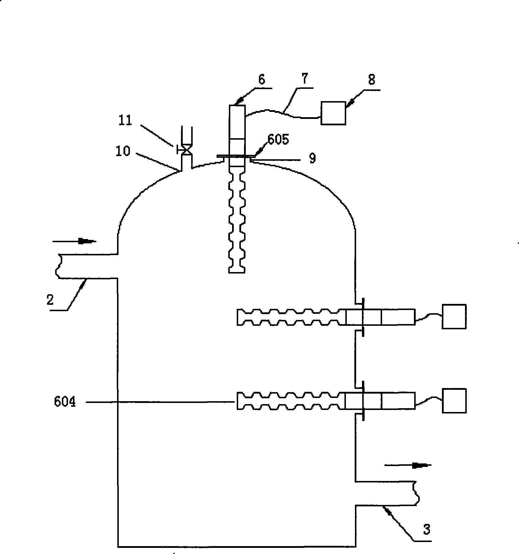
[0025] Such as figure 1 As shown, an emulsion ultrasonic demulsification device adopted in the present embodiment includes a vertical or tower chamber 1, an exhaust port 10 and its corresponding exhaust valve 11 are arranged on the top of the chamber 1, The input port 2 of the emulsion is located at the upper part of the vertical cavity, and the output port 3 of the emulsion is arranged at the lower part of the cavity, and the liquid in the cavity is used to act on the liquid in the cavity or a columnar ultrasonic vibration system, according to the shape of the cavity 1 and Volume, at least one set of ultrasonic vibration system 6 is evenly distributed on the top and side of the cavity in turn, so that the emulsion in the cavity can obtain the largest uniform action area. During the slow movement from top to bottom, the emulsion in the cavity is irradiated by omni-directional ultrasonic waves emitted by at least one ultrasonic device, and the action time is prolonged. The ele...

Embodiment 2

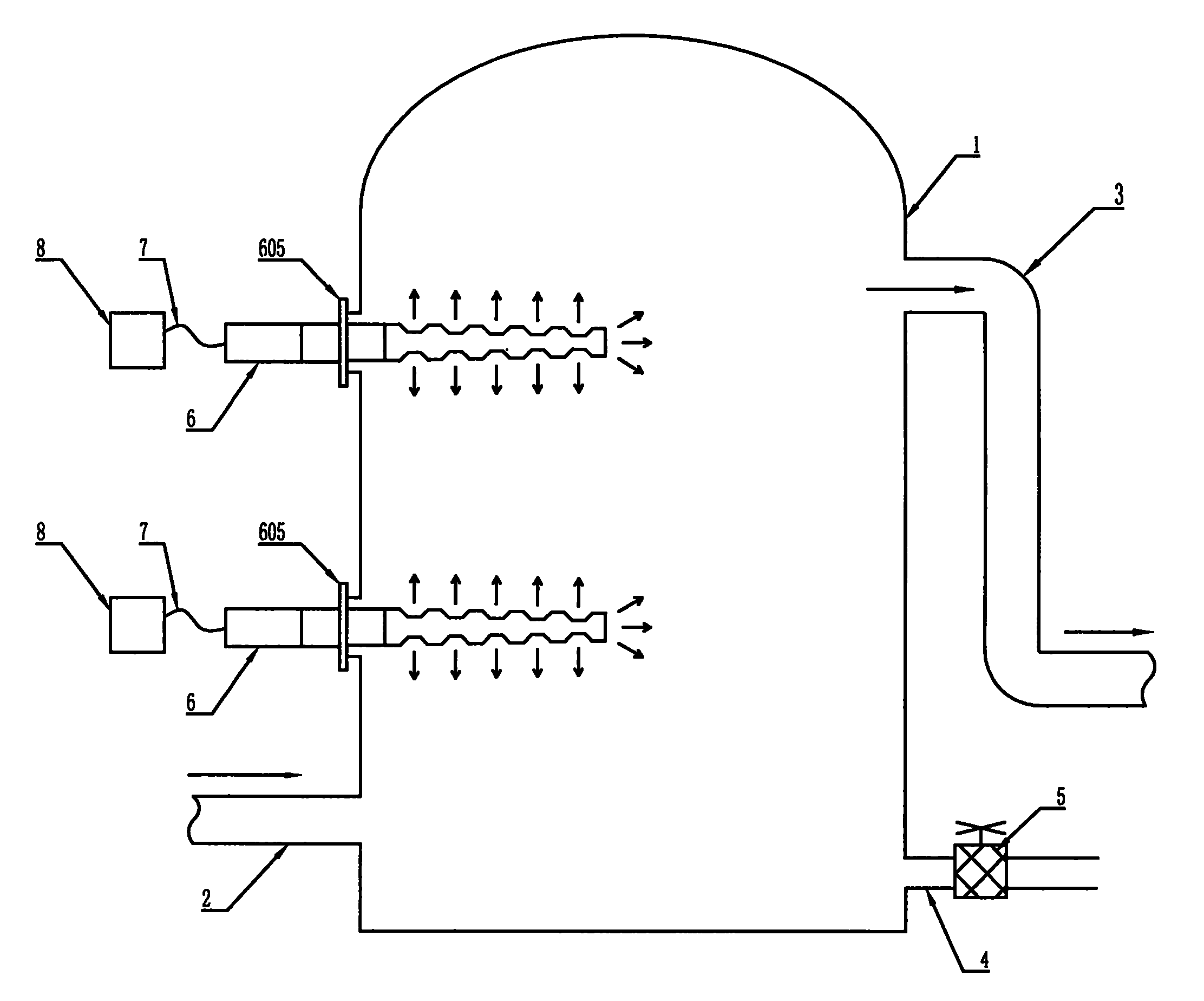
[0028] Such as figure 2As shown, an ultrasonic demulsification device adopted in this embodiment includes a vertical or tower chamber 1, the input port 2 of the emulsion is arranged near the lower part of the chamber, and the output port 3 of the emulsion is arranged In the upper part of the cavity 1, in order to avoid the accumulation of detached water at the bottom of the cavity after working for a long time, there is also a drain pipe 4 and a corresponding control valve 5 at the bottom of the cavity for The part of the effusion with a relatively large specific gravity in the emulsion is discharged, and at least one set of ultrasonic vibration system is installed on the wall of the cavity through the flange 9. The transverse maximum dimension (diagonal) of the transducer part 601 of the ultrasonic vibration system is 57mm, the cross-sectional diameter of the protruding part in the middle of the rod body of the tool head 603 and the diameter of the front end surface 604 are ...

Embodiment 3

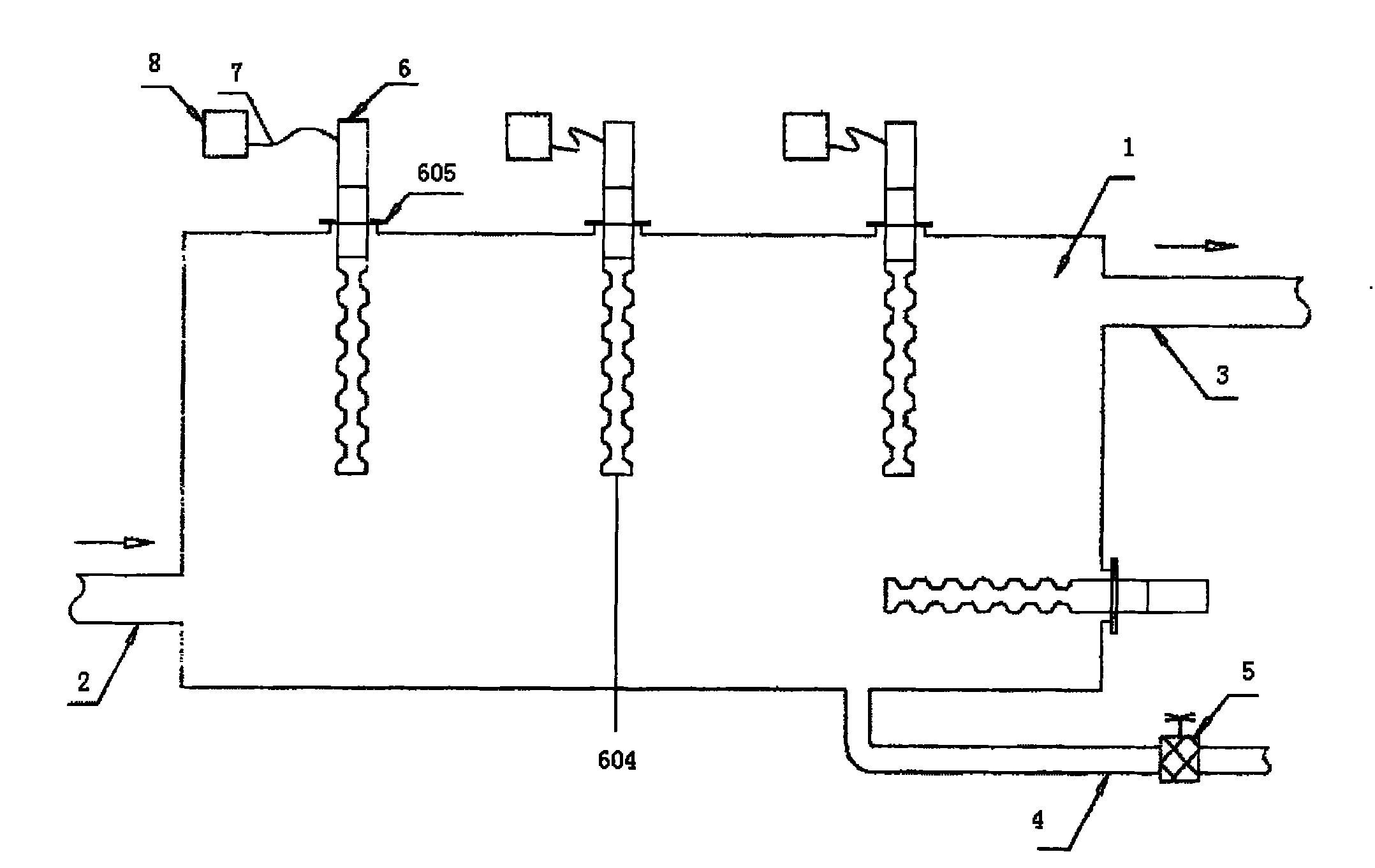
[0030] Such as image 3 As shown, an ultrasonic demulsification device used in this embodiment includes a horizontal cavity 1, the diameter of which is much larger than that of the input and output pipelines, generally greater than twice. The input port 2 of the emulsion is set near the lower part of the cavity, and the output port 3 of the emulsion is set at the upper part of the cavity. The emulsion entering the cavity is emitted by the ultrasonic generator installed on the side of the cavity during the slow flow process. In order to avoid the accumulation of prolapsed water at the bottom of the cavity after long-term work, a drain pipe 4 and a corresponding control valve 5 are also provided at the bottom of the cavity to drain the The part of the effusion with a relatively large specific gravity in the emulsion is discharged, and at least one set of ultrasonic vibration system is installed on the wall of the cavity through the flange 9, and the transverse maximum dimension ...


PUM

PropertyMeasurementUnit
diameteraaaaaaaaaa

Abstract

The invention relates to an emulsion ultrasonic emulsion breaking device, which comprises a cavity provided with an input port and an output port, wherein the input port and the output port are arranged on the cavity in an upper-lower matched pair or a lower-upper matched pair, namely the input port is arranged close to the lower end of the cavity, the corresponding output port is arranged close to the upper end of the cavity, and vice versa; and the wall of the cavity is provided with at least one ultrasonic wave generating device through flanges, and a tool head of the ultrasonic wave generating device has a candied gourd shape and is arranged in the cavity. Under the action of the gravity, the emulsion ultrasonic emulsion breaking device achieves balanced flow of an emulsion in an acting cavity, adopts an ultrasonic vibration system, makes full use of ultrasonic waves sent to the circumference from a lateral surface of a rod by the ultrasonic tool head immerged into the emulsion toenlarge the action zone of the ultrasonic waves in the cavity as large as possible, and improves the efficiency and the effect of ultrasonic emulsion breaking. The emulsion ultrasonic emulsion breaking device is adaptable to oil-water emulsion breaking separation.

Description

technical field [0001] The invention relates to a device for demulsification and separation of oil-water emulsion, in particular to an emulsion ultrasonic demulsification device for accelerating oil-water separation by means of ultrasonic waves. Background technique [0002] In petroleum, petrochemical and other industrial production, an important process is to open the tightly bound "water-in-oil" or "oil-in-water" particles, that is, to break the emulsion, and then use the density difference between oil and water , at a certain temperature, the complete separation of oil and water is achieved through sedimentation, centrifugation, etc. At present, in addition to using ordinary thermochemical demulsification in industrial production, that is, adding a chemical demulsifier to the emulsion to speed up the oil-water separation process, the vibration and cavitation of the ultrasonic wave acting on the liquid are used to realize the oil-water emulsion. Demulsification and dehyd...

Claims


Application Information

Patent Timeline
Patent Type & Authority Patents(China)
IPC IPC(8): B01D17/04C10G33/06
Inventor 王其明李安星李文琦孙延佩宫志桦朱更君
Owner WEIHAI HAIHER TECH
Learn More