
Method and device for polishing magneto-rheological inclined shaft

A polishing device and magneto-rheological technology, applied in the direction of grinding/polishing equipment, optical surface grinders, grinding machines, etc., can solve the problems of low precision, broken shape precision, lack of flexibility, etc., to reduce the intermediate transmission links and reduce the size Requirements, the effect of simple and compact structure

Inactive Publication Date: 2009-10-28
HUNAN UNIV
View PDF1 Cites 38 Cited by
  • Summary
  • Abstract
  • Description
  • Claims
  • Application Information

AI Technical Summary

Problems solved by technology

[0003] The traditional polishing mold polishes optical glass, which has some disadvantages: different materials need to use polishing molds with different hardness; it will produce sub-surface damage, which will affect the surface quality of optical parts; lack of flexibility, resulting in surface shape errors on the surface of the workpiece
Due to the use of fluid clusters for impact polishing, this method has low precision and is difficult to control, and it is also difficult to be used for polishing small parts
For the ultra-precision grinding of tiny spherical and aspheric parts with a size below 8 mm, due to the narrow processing space, it is difficult to implement the traditional viscoelastic polishing head combined with the polishing process of free abrasives, and the quality of the polished surface is uneven. Will destroy the shape accuracy obtained in the previous process
[0004] The electromagnetic magneto-rheological polishing head proposed in patent 03153996.3 is similar to the polishing wheel method used by QED, which is difficult to control accurately and cannot process tiny parts

Method used


Image

  • Method and device for polishing magneto-rheological inclined shaft
  • Method and device for polishing magneto-rheological inclined shaft
  • Method and device for polishing magneto-rheological inclined shaft

Examples


Embodiment Construction

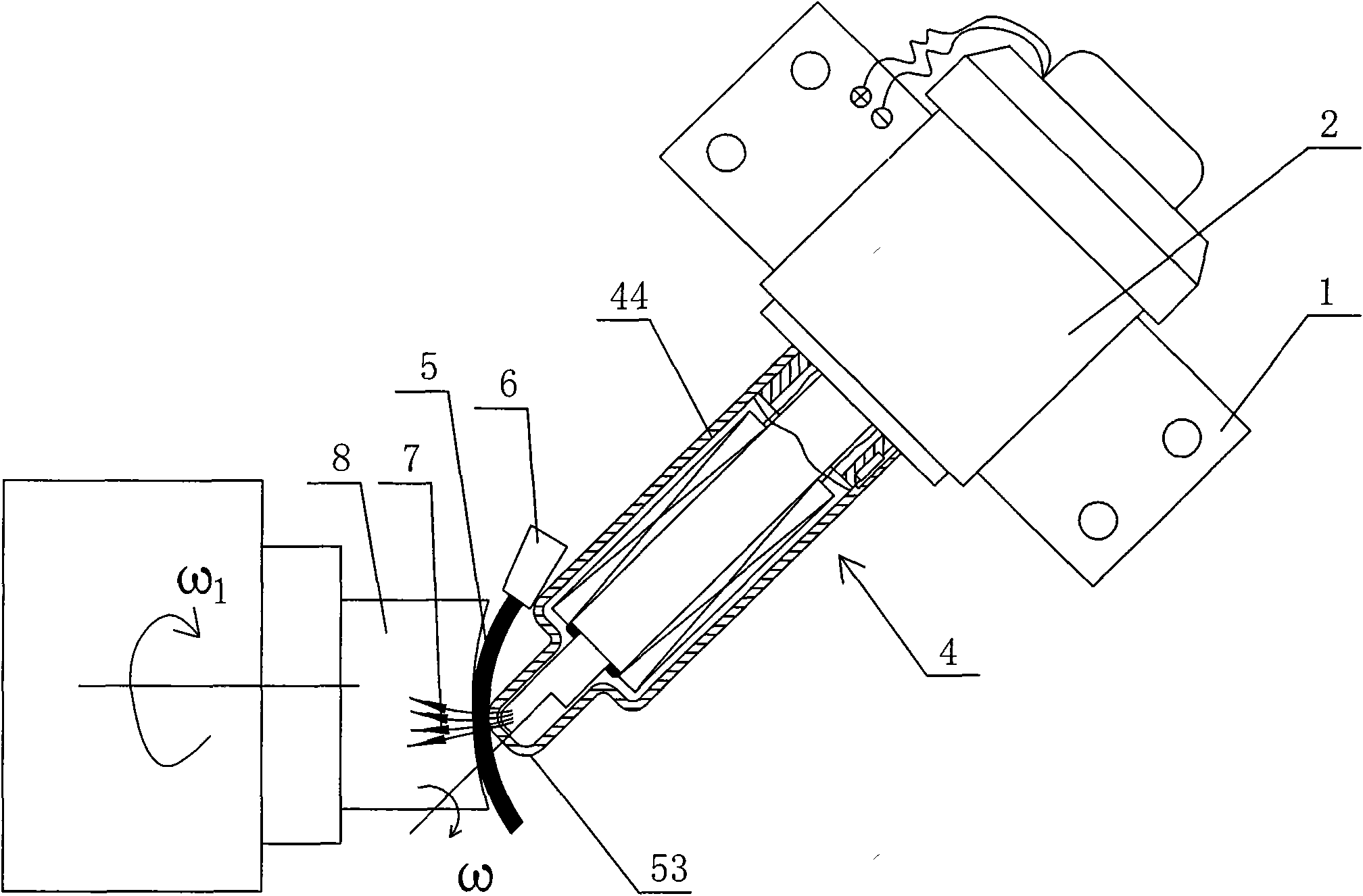
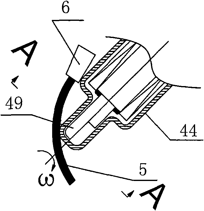
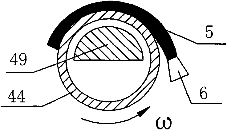
[0047] see figure 1 , figure 2 , image 3 , the magnetorheological polishing head support 1 of the present invention is installed on the motion table of the ultra-precision machine tool at a certain angle, so that the working arc normal of the polishing head coincides with the normal of the workpiece polishing surface, and oblique axis grinding and polishing is performed on the workpiece 8.

[0048] The inclined-axis polishing device has a speed-regulating motor 2 mounted on the support 1, the main shaft of the speed-regulating motor 2 is a hollow shaft 42, the rear end of the polishing head shell 44 is fixedly connected with the hollow shaft 42, and the polishing head shell The rear end of the fixed shaft 3 in 44 passes through the hollow shaft 42 and is fixedly connected with the speed regulating motor 2 body; the fixed shaft 3 is equipped with an excitation device 43, and the front end of the fixed shaft 3 is fixedly connected with an easy Magnetized body 46; see Figu...


PUM


Abstract

A method and a device for polishing a magneto-rheological inclined shaft relate to the technical field of precise finishing machining. A polishing tool head and the axial direction of a workpiece have an angle so that the normal of the working arc of the polishing tool head is coincident with the polishing surface normal of the workpiece; the shell of the polishing tool head rotates; furthermore, the rear end of the shaft in the shell passes through the hollow shaft of an adjustable speed motor and is fixedly connected with a machine body; the fixed shaft is provided with an excitation device; one part of the small front area of the shell of the polishing tool head is provided with a magnetic field and the other part thereof has no magnetic field or has weak magnetic field, thus facilitating updating the magneto-rheological liquid; the contact point of the workpiece and the magneto-rheological point is always the normal direction of the polishing area of the workpiece; the shell of the polishing tool head rotates and the magneto-rheological body generates a high shearing force at the clearance between the polishing tool head and the workpiece, thus removing trace of the material. By adopting the inclined shaft polishing, the interference is prevented from being generated; by planning path and controlling relevant parameters, the specific ultra-precise polishing process can be carried out to the surfaces of minitype non-spherical optical parts, dies and workpieces of general dimensions.

Description

technical field [0001] The invention relates to precision finishing technology, and further refers to a precision polishing tool suitable for grinding and polishing tiny aspheric optical parts and molds thereof. Background technique [0002] In high-precision optical systems, high-quality aspheric mirrors are widely used, and the processing and manufacturing requirements of these optical components and their molds are very high. The processing of optical components and their molds is mainly completed by ultra-precision processes such as grinding and turning, but these processed surfaces will produce sub-surface damage after grinding and turning. Therefore, the sub-surface must be eliminated by subsequent ductile polishing process Damage to improve optical imaging quality. At present, the main optical grinding and polishing can be carried out through traditional polishing molds, magnetorheological fluid polishing wheels, or magnetic jet polishing. [0003] The traditional p...

Claims


Application Information

Patent Timeline
IPC IPC(8): B24B13/00B24B13/01B24B19/20
Inventor 尹韶辉陈逢军唐恒宁范玉峰朱永建
Owner HUNAN UNIV
Learn More