Pulse thermal fin plate type radiator

A plate heat exchanger and pulse technology, applied in indirect heat exchangers, electric solid devices, semiconductor devices, etc., can solve the problems of inability to meet the heat dissipation requirements of high-power LEDs, low heat dissipation efficiency, and high manufacturing costs, and achieve light weight, High heat dissipation efficiency and low manufacturing cost

Active Publication Date: 2009-10-28
NANJING UNIV OF TECH
View PDF0 Cites 10 Cited by
  • Summary
  • Abstract
  • Description
  • Claims
  • Application Information

AI Technical Summary

Problems solved by technology

[0003] Traditional cooling technologies either have a simple structure but low heat dissipation efficiency (air-cooling heat dissipation technology), or high heat dissipation e

Method used


Image

  • Pulse thermal fin plate type radiator
  • Pulse thermal fin plate type radiator
  • Pulse thermal fin plate type radiator

Examples


Embodiment 1

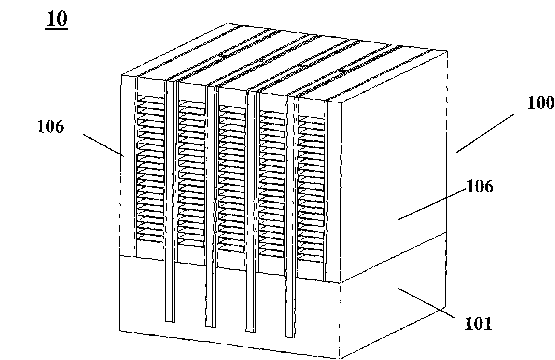
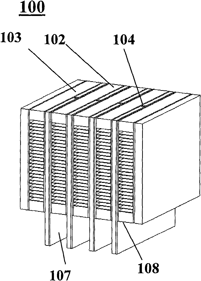
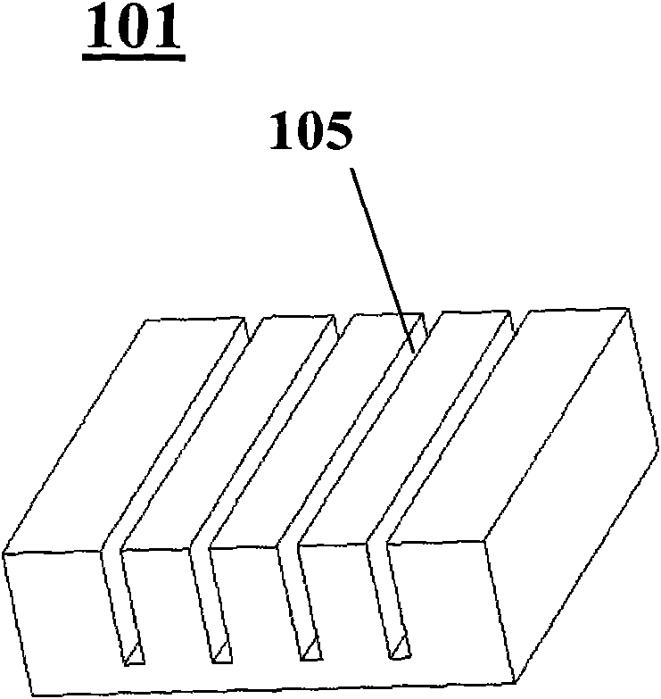
[0025] refer to figure 1 and figure 2 , The pulse heat fin plate type is composed of a core body 100 and a vapor chamber 101, and the core body 100 and the vapor chamber 101 are made of aluminum with good thermal conductivity. The core body 100 is composed of several pulsed hot plates 102 and plate-fin channels 103 interspersed with each other, stacked and brazed from left to right, so as to realize the phase change heat transfer at the pulse self-excited oscillation interface between the cold air and the working medium. Both sides of the core body 100 are provided with cover plates 106 . The temperature equalization plate 101 is used to pass heat evenly to each pulse hot plate. The upper end of the pulse microchannel plate 102 is provided with a liquid filling port 104, which is used to evacuate the inside of the pulse hot plate and fill it with a working medium, which is deionized water. The liquid filling port 104 is equipped with a connecting pipe, and the way of seali...

Embodiment 2

[0030] Refer to attached Figure 8 and Figure 9 , the lower end surface of the vapor chamber 101 of the pulse heat finned radiator is assembled with the LED lamp 300, and the rear end of the fin channel 103 is equipped with a small fan 200 for providing cold air to the radiator 10 for forced convection heat dissipation.

[0031] Refer to attached Figure 10 The heat emitted by the high-power LED lamp 300 at the bottom of the pulse heat fin plate radiator 10 is transferred to the vapor chamber 101, and the vapor chamber 101 makes the heat evenly transmitted to the evaporation end of each pulse plate to heat the working fluid to cause nucleate boiling , forming a vapor plug 109 and a liquid plug 108 in the U-shaped micro-channel 203 of the pulse hot plate to generate pulse oscillation and circulation. Relying on thermally induced self-excited oscillation to generate a dynamic interfacial phase transition phenomenon, the heat is transferred to the cold air in the plate-fin cha...


PUM


Abstract

The invention relates to a pulse thermal fin plate type radiator, which has the advantages of compact structure and function, small volume, light weight, long service life, high radiating efficiency and low manufacturing cost. The aim of the invention is achieved through the following technical proposal: the pulse thermal fin plate type radiator are formed by connecting a core body and a temperature-uniforming plate up and down, wherein the core body is formed by mutual interpenetration and transverse superposing soldering of a plurality of pulse heating plates and plate-fin type channels, and evaporation ends of the pulse heating plates are lower than the bottom surfaces of the plate-fin type channels; the pulse heating plates consist of pulse microchannel plates and clapboards, surface pulse heating plates of the pulse microchannel plates opposite to the clapboards are provided with pulse channels, and the upper ends of the pulse microchannel plates are provided with fluid-filling openings communicated with the pulse channels; and the temperature-uniforming plate is provided with slots corresponding to the plurality of the pulse heating plates, and the evaporation ends of the pulse microchannel plates are inserted in the slots.

Description

technical field [0001] The invention relates to a heat sink, in particular to a pulse heat fin plate type heat sink used for heat dissipation of high-power LED lamps. Background technique [0002] As a solid light source, LED (Light Emitting Diode) light-emitting diodes ignite the brilliance of "green lighting" and are considered to be the most valuable new light source in the 21st century. They will replace incandescent lamps and fluorescent lamps and become the leading lighting market. During the working process of LED, about 75%~85% of the electric energy is converted into heat energy. With the increase of LED power, the heat generation increases, and the heat dissipation problem of LED lighting system has become a major obstacle restricting the development of this technology. [0003] Traditional cooling technologies either have a simple structure but low heat dissipation efficiency (air-cooling heat dissipation technology), or high heat dissipation efficiency but comple...

Claims


Application Information

Patent Timeline
IPC IPC(8): F21V29/00H01L23/34H01L23/427F21Y101/02F21V29/51F21V29/67F21Y115/10
CPCF28D15/0266
Inventor 凌祥杨新俊
Owner NANJING UNIV OF TECH
Why Eureka
Try Eureka