Biaxial optical gyroscope

An optical gyroscope and optical chip technology, applied in the field of integrated optical and inertial sensors, can solve problems such as single function, inability to achieve simultaneous measurement of multi-axis space, etc., to achieve the effect of improving utilization

Active Publication Date: 2009-10-28
SOUTHEAST UNIV
View PDF0 Cites 14 Cited by
  • Summary
  • Abstract
  • Description
  • Claims
  • Application Information

AI Technical Summary

Problems solved by technology

At present, the optical gyroscope in the application mainly realizes the single-axis measurement function, which has a single function and cannot realize the simultaneous measurement of multi-axis space. The development and development requirements of sensors

Method used


Image

  • Biaxial optical gyroscope
  • Biaxial optical gyroscope
  • Biaxial optical gyroscope

Examples


Embodiment Construction

[0018] The technical solution of the present invention will be further described below in conjunction with the accompanying drawings.

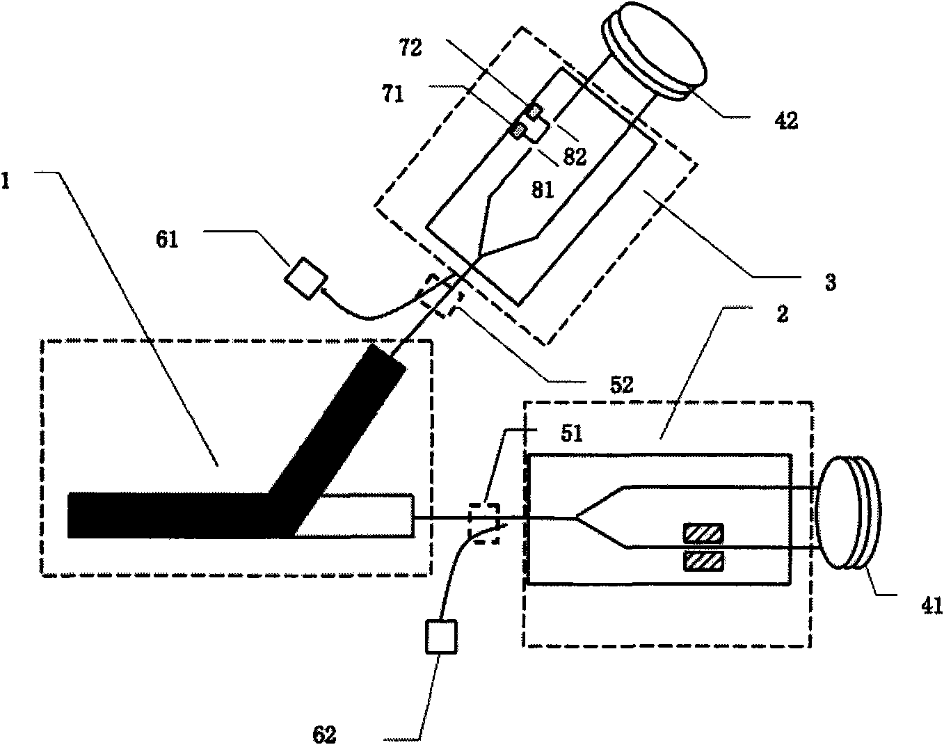
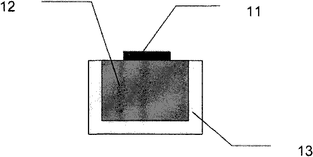
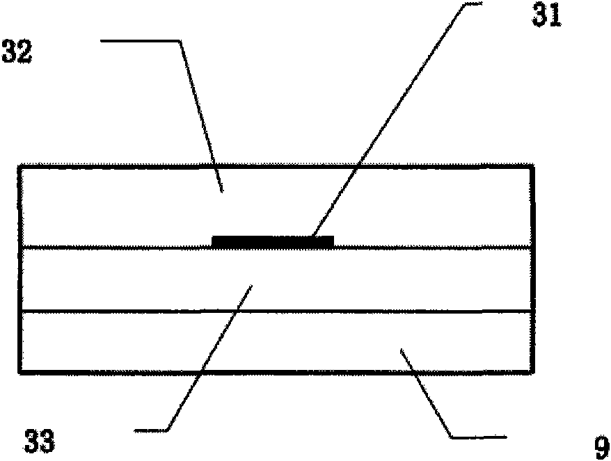
[0019] The two-axis optical gyroscope proposed by the present invention, from a structural point of view, the optical gyroscope consists of a surface plasmon Y-type mode separator 1, a Y-waveguide integrated optical device 2, a Y-waveguide integrated optical chip 3, and a first polarization-maintaining fiber coil 41. The second polarization-maintaining fiber coil 42, directional couplers 51, 52, and detectors 61, 62 are composed; the positional relationship is that the two output ends of the surface plasmon polariton Y-type mode separator 1 are respectively connected with the Y-waveguide integrated optical device 2 , Y waveguide integrated optical chip 3 are connected, the output ends of Y waveguide integrated optical device 2 and Y waveguide integrated optical chip 3 are respectively connected with the first polarization-maintaining fiber coil...


PUM


Abstract

The invention relates to a biaxial optical gyroscope, which consists of a surface plasma excimer Y-type mode separator, a Y waveguide integrated optical device, a Y waveguide integrated optical chip, a first polarization-preserving fiber coil, a second polarization-preserving fiber coil, a directional coupler and a detector. The invention belongs to the technical field of integrated optics and inertial sensor, and provides the biaxial optical gyroscope. The biaxial optical gyroscope with a separation mode is realized by adopting waveguide devices made of different materials, and has the advantages of improvement on the utilization rate of light sources, high integrity and the like.

Description

technical field [0001] The invention belongs to the technical field of integrated optics and inertial sensors, in particular to a two-axis optical gyroscope. Background technique [0002] Optical gyroscopes are important test components for inertial navigation, inertial guidance and control testing equipment. The optical gyroscope is a new type of photoelectric gyroscope based on the Sagnac effect, and the development of its technology is closely related to the development of the gyroscope. The performance of the inertial guidance system largely depends on the performance of the gyroscope. Therefore, the technical level of the gyroscope directly affects the performance indicators of the inertial navigation system and the inertial guidance device. At present, the optical gyroscope in the application mainly realizes the single-axis measurement function, which has a single function and cannot realize the simultaneous measurement of multi-axis space. The development and resear...

Claims


Application Information

Patent Timeline
Patent Type & Authority Applications(China)
IPC IPC(8): G01C19/64
CPCG01C19/721G02B6/1226B82Y20/00
Inventor 张彤薛晓军张晓阳吴朋钦陈秋月
Owner SOUTHEAST UNIV
Why Eureka
Try Eureka