Balloon expandable stent with side-hole channel

A technology of balloons and side holes, which is applied in the direction of stents, medical devices, and devices of human tubular structures. It can solve problems such as the displacement of stents or embolisms, the addition of devices and links, and the unfavorable passage of blood, so as to overcome the displacement. or falling off, increasing the success rate and reducing the difficulty of surgery

Inactive Publication Date: 2009-11-04
赵林
View PDF0 Cites 28 Cited by
  • Summary
  • Abstract
  • Description
  • Claims
  • Application Information

AI Technical Summary

Problems solved by technology

In some existing operations, after the stent is implanted in the main blood vessel, the micro guide wire is used to find the mesh of the stent, and then go through the mesh of the stent for further surgery, but the operation of finding the mesh of the stent is difficult, which usually leads to the failure of further surgery ; In some operations, a stent is released on the branch first, and the stent part protrudes into the lumen of the main vessel, and then a stent is released in the main vessel, so that there is a three-layer stent network structure at the opening of the side branch vessel, which is very unfavorable for blood to pass through. , and prone to thrombosis
[0005] For wide-necked aneurysms, in the stent-assisted embolization of wide-necked aneurysms, in order to avoid the work of finding the mesh of the stent, another microcatheter is placed between the stent and the vessel wall in advance, and the balloon is released to release the stent. After the aneurysm is embolized, the microcatheter is extracted from between the stent and the vessel wall. This surgical method increases the number of instruments and links used, and there is a risk of displacement of the stent or embolism

Method used


Image

  • Balloon expandable stent with side-hole channel
  • Balloon expandable stent with side-hole channel
  • Balloon expandable stent with side-hole channel

Examples


Embodiment Construction

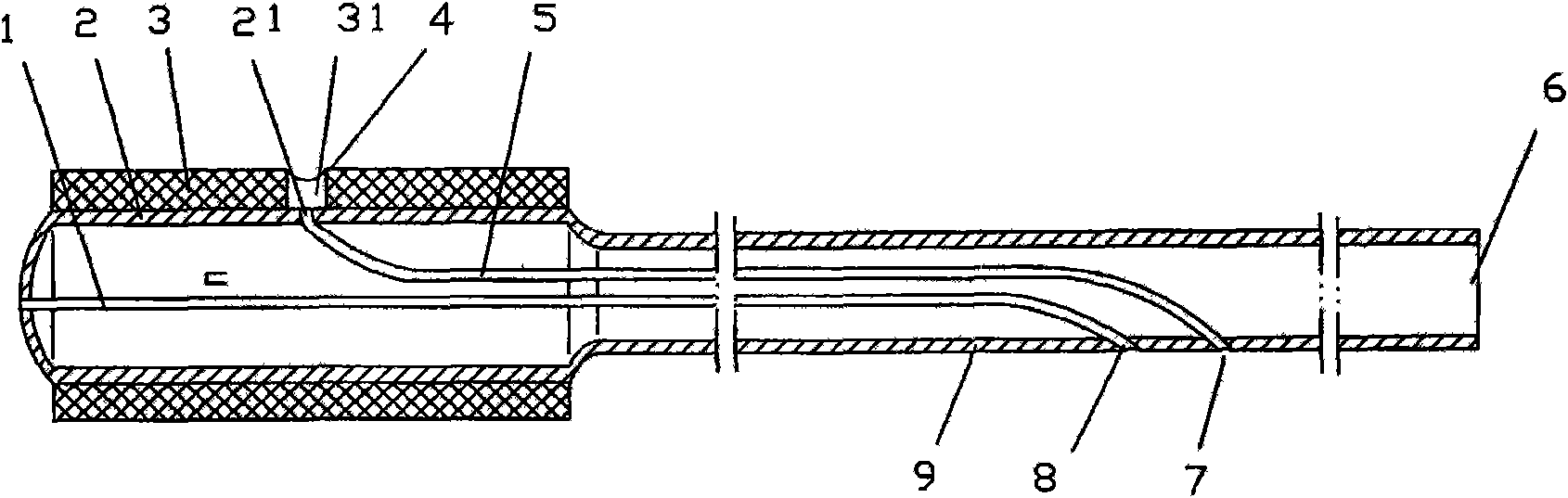
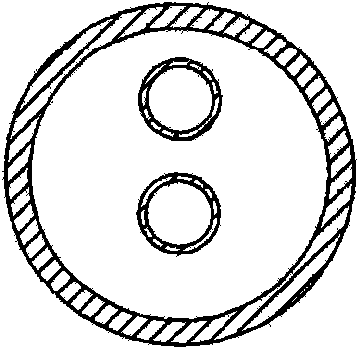
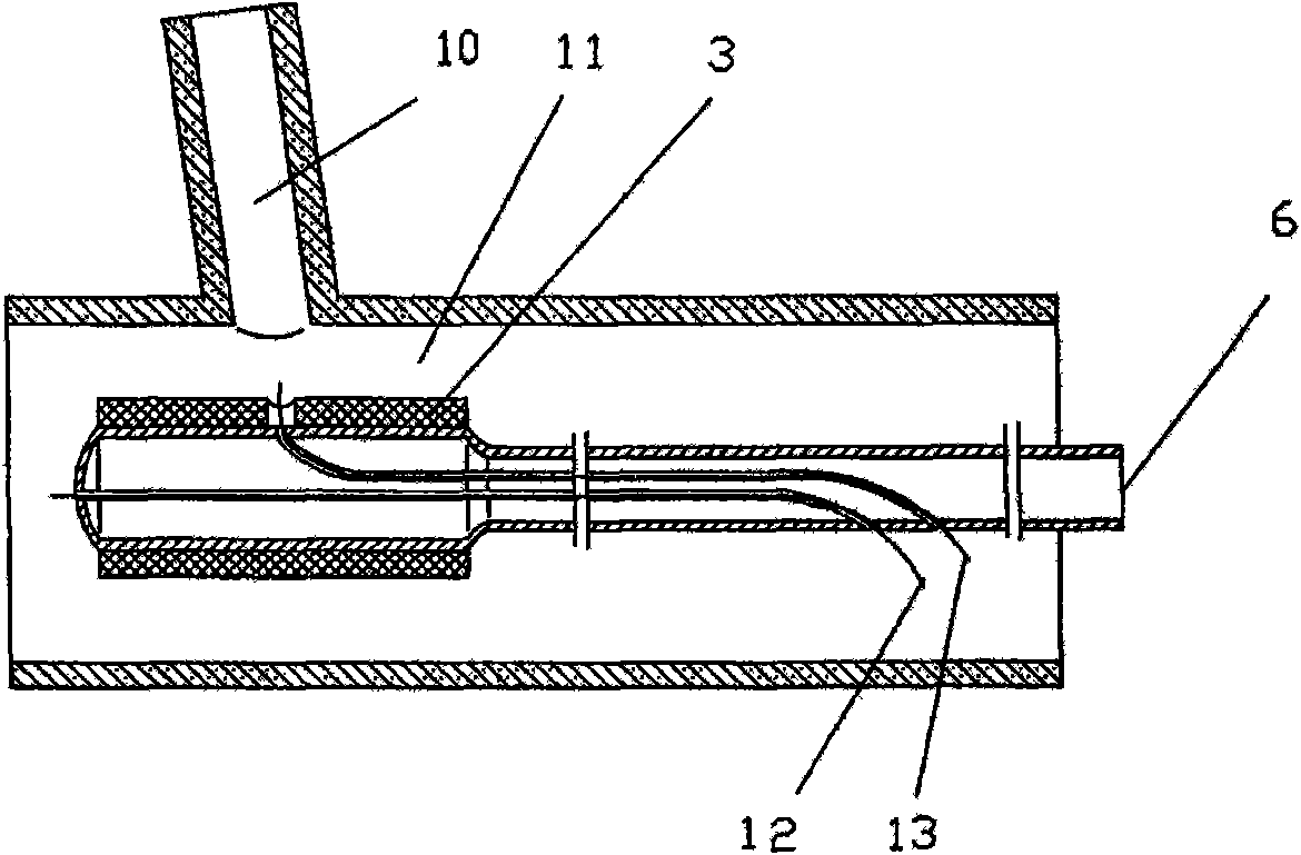
[0019] see Figure 1 ~ Figure 3 , the balloon-expandable stent with a side hole channel includes a balloon 2, one end of the balloon 2 communicates with a balloon catheter 9 for injecting and aspirating a contrast agent, and an expandable compression stent 3 is installed on the outside of the balloon 1 (the stent leaves the factory. When pressing and holding outside the balloon), it is characterized in that: the balloon 2 and the balloon catheter 9 are provided with an inner cavity main channel 1 that can pass through the micro guide wire and an inner cavity branch channel 5 that can pass the micro guide wire, and the inner cavity One end of the main channel 1 opens to the side wall of the balloon catheter 7, and the other end opens to the top of the balloon 2; one end of the lumen branch channel 5 opens to the side wall of the balloon catheter 9, and the other end opens to the side of the balloon 2 Wall; the expandable compression stent 3 is provided with a side hole 31 oppos...


PUM


Abstract

The invention relates to a balloon expandable stent with a side-hole channel, which belongs to the technical field of medical devices implantable into the blood vessel of human body. One end of the balloon is communicated with a balloon catheter that can inject and suck out contrast agent; an expandable compression stent is arranged outside the balloon; a main intracavity channel and an intracavity sub-channel are respectively arranged in the balloon and the balloon catheter; one opening of the main intracavity channel is positioned at the side wall of the balloon catheter, and the other opening is positioned at the top of the balloon; one opening of the intracavity sub-channel is positioned at the side wall of the balloon catheter, and the other opening is positioned at the side wall of the balloon; the expandable compression stent is provided with a side hole opposite to the side-wall hole of the balloon. The invention has the characteristics of simple structure, convenient operation and use, time saving and safety; meanwhile, the stent can break through the forbidden zone that the interventional therapy can not proceed due to the bifurcation and lesion of the blood vessel of brain, can simplify the steps of treating the bifurcation and lesion of the coronary artery, lower the operation risk and difficulty of stent-aiding embolism operation for wide-necked aneurysms, enhance interventional embolism / surgical clipping ratio, and alleviate patients' wound and pain.

Description

technical field [0001] The invention belongs to the technical field of medical appliances that can be implanted into human blood vessels. Background technique [0002] The existing balloon-expandable stent is a pre-installed stent outside the balloon catheter. The stent is pressed outside the balloon when it leaves the factory. The whole system can pass through the catheter with an inner diameter of ≤2mm (6F), and some of them need to pass through 8F (3F= 1mm) inside the catheter. The balloon catheter has 2 coaxial lumens, one lumen is the guide wire lumen, and a micro guide wire with a diameter of 0.008-0.014 inches (1 inch = 2.54cm) can pass through the guide wire lumen, along which the guide wire balloon catheter Advance in the blood vessel; another lumen leads to the balloon, and the balloon is inflated by injecting contrast agent, so that the stent expands and sticks to the inner wall of the blood vessel, and then the contrast agent is drawn out to deflate the balloon,...

Claims


Application Information

Patent Timeline
Patent Type & Authority Applications(China)
IPC IPC(8): A61F2/82A61F2/06A61M31/00A61F2/958
Inventor 赵林
Owner 赵林
Why Eureka
Try Eureka