
Membrane oxygenator

A membrane oxygenator and oxygenation technology, applied in dialysis systems and other directions, can solve the problems of inconvenient operation, large space for connecting pipelines, and increase the length of hoses, and achieve easy hose connection, reduction of cavity space, The effect of preventing blood blister phenomenon

Active Publication Date: 2012-05-02
DONGGUAN KEWEI MEDICAL INSTR CO LTD
View PDF5 Cites 0 Cited by
  • Summary
  • Abstract
  • Description
  • Claims
  • Application Information

AI Technical Summary

Problems solved by technology

This creates a problem. When the hose is rotated, the coiled hose is not only easy to form a fetter, but also increases the length of the hose, which invisibly increases the blood preflush volume of the oxygenator.
In addition, it is inconvenient to coil the hose to insert it into the corresponding interface
[0010] 2. In the traditional membrane oxygenator: the oxygenation chamber and the variable chamber adopt an integrated structure, or are formed separately and then connected to form
[0011] 1. The cavity space of the connecting pipe is large, resulting in more blood contained in the connecting pipe, which leads to an increase in the prefilling volume of blood
[0012] 2. The current pipeline connection structure is cumbersome and difficult to operate
[0013] 3. During the oxygenation and exchange process of the current membrane oxygenator, if the fiber membrane tube in the oxygenation chamber breaks, the gas in the fiber membrane tube will leak and mix into the blood in the gap of the fiber membrane tube
In order to prevent the patient from transfusing gas-laden blood, the blood bubble must be processed later, which increases the operating procedures

Method used


Image

  • Membrane oxygenator
  • Membrane oxygenator
  • Membrane oxygenator

Examples


Embodiment Construction

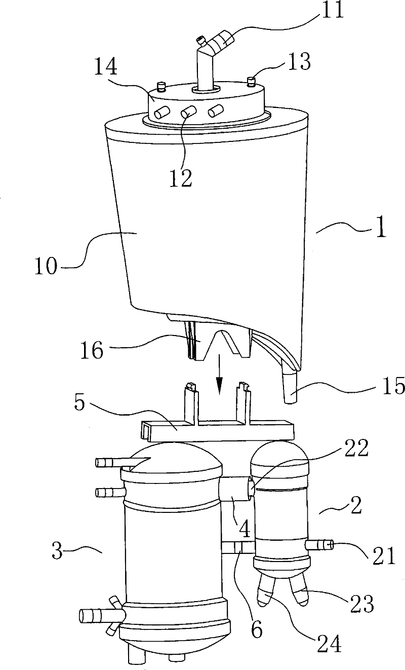
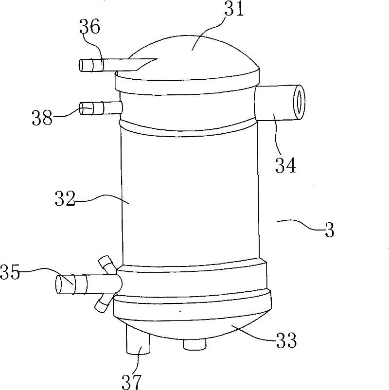
[0036] See figure 1 , which is a structural schematic diagram of the membrane oxygenator of the present invention. The present invention includes: a blood storage chamber 1 with a storage function, an oxygenation chamber 3 and a variable chamber 2 for regulating blood temperature. Wherein, the temperature-changing chamber 2 communicates with the oxygenation chamber 3 through a pipeline connecting device 4 .

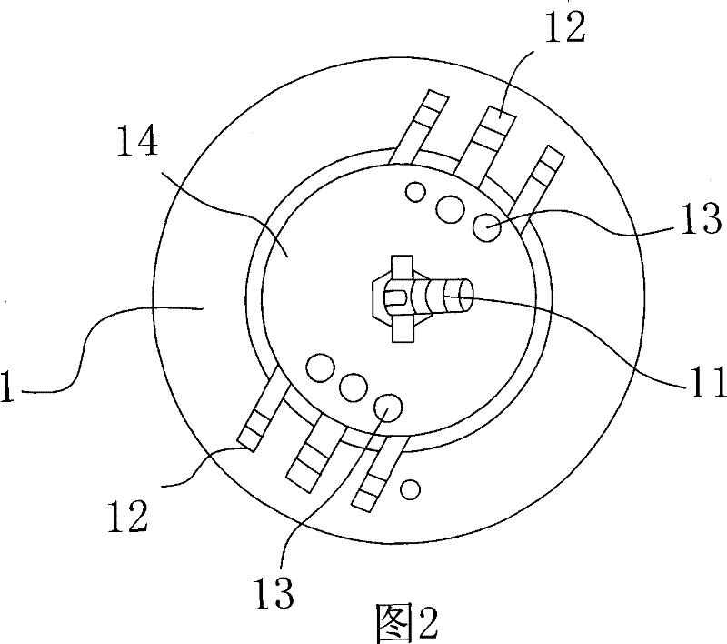
[0037] see figure 1 , 2 The main body of the blood storage chamber 1 is a chamber 10 for storing blood, and the chamber 10 is provided with a venous blood drainage nozzle 11 and several suction nozzles 12 communicating with the inner cavity of the chamber 1 . Wherein, a turntable 14 is rotatably installed on the upper end cover of the chamber 10, and the suction nozzle 12 is arranged on the peripheral side of the turntable 14. The venous blood drainage nozzle 11 is arranged at the center of the upper end surface of the turntable 14 , and a rotatable pivot structure is ...


PUM


Abstract

The invention relates to the technical field of medical appliance products, in particular to a membrane oxygenator which comprises a blood storage room, a temperature change room and an oxygenating room, wherein an upper connecting rack is arranged below the blood storage room; the temperature change room and the oxygenating room are fixedly connected through a lower connecting rack; the upper connecting rack and the lower connecting rack are buckled and matched with each other; and the temperature change room and the oxygenating room are communicated through a pipeline connecting device. Theintegral structure of the membrane oxygenator can be disassembled and can be assembled conveniently and stably. In addition, a venous blood drainage nozzle and an absorption nozzle on the blood storage room can be independently rotated at 360 degrees so as to be convenient for connecting a flexible pipe and can reduce the precharge quantity of blood. The structure of the oxygenating room can prevent the phenomenon of blood bubbles, and the pipeline connecting device adopted by the temperature change room and the oxygenating room can shorten the length of a connecting pipeline so as to ensure that a cavity space of the connecting pipeline is reduced, thus, the precharge quantity of the blood can be reduced.

Description

Technical field: [0001] The invention relates to the technical field of medical device products, in particular to a membrane oxygenator. Background technique: [0002] Extracorporeal membrane oxygenation as a medical technique is mainly used in cardiac surgery. This technology can completely replace the heart and lungs in the short term to perform open-heart surgery. Its principle is to draw the venous blood in the body out of the body, and inject it into the patient's arterial or venous system after being oxygenated by artificial cardiopulmonary bypass with special materials, so as to play a part of cardiopulmonary replacement and maintain the oxygenated blood supply of human organs and tissues. [0003] An oxygenator is usually used in this technique. Its function is to synthesize oxygenated blood from non-oxygenated blood, also known as artificial lung. Oxygenators generally include membrane oxygenators and hollow fiber oxygenators. Among them, the membrane oxygenator...

Claims


Application Information

Patent Timeline
Patent Type & Authority Patents(China)
IPC IPC(8): A61M1/14A61M1/16
Inventor 刘丙戌
Owner DONGGUAN KEWEI MEDICAL INSTR CO LTD
Learn More