Backboard structure of backlight module

A backlight module and backplane technology, applied in optics, nonlinear optics, lighting devices, etc., can solve the problems of complexity, high process and material cost, consumption, etc.

Inactive Publication Date: 2009-11-04
CENTURY DISPLAY (SHENZHEN) CO LTD
View PDF0 Cites 17 Cited by
  • Summary
  • Abstract
  • Description
  • Claims
  • Application Information

AI Technical Summary

Problems solved by technology

[0005] see Figure 1 to Figure 3 As shown, it has a metal backplane 10, a driver circuit board 11 (source driver IC; COF) is provided on one side of the metal backplane 10, and the driver circuit board 11 is connected with a printed circuit board (Printed circuit board, PCB) 12, and the metal The other side of the back plate 10 is provided with a light guide plate 15 and a liquid crystal panel composed of a color filter 14 and a glass substrate 13 in sequence, and a plastic frame 16 is placed between the front and rear ends of the metal back plate 10 and the glass substrate 13 In the meantime, the components can be fixed in an iron frame 17 after being combined; the above-mentioned method is to form a bump (crater-like) 18 on the metal back plate 10 by stamping, and then use this bump 18 as a fixed printed circuit board 12, and The printed circuit board 12 has many holes (vias), so there is a possibility of a short circuit where the metal backplane 10 and the printed circuit board 12 are fixed, so insulating rubber 19 is generally used to cover the metal backplane 10 and the bumps 18 In order to facilitate insulation; therefore, for the production process, it is quite complicated and must consume high process and material costs

Method used


Image

  • Backboard structure of backlight module
  • Backboard structure of backlight module
  • Backboard structure of backlight module

Examples


Embodiment Construction

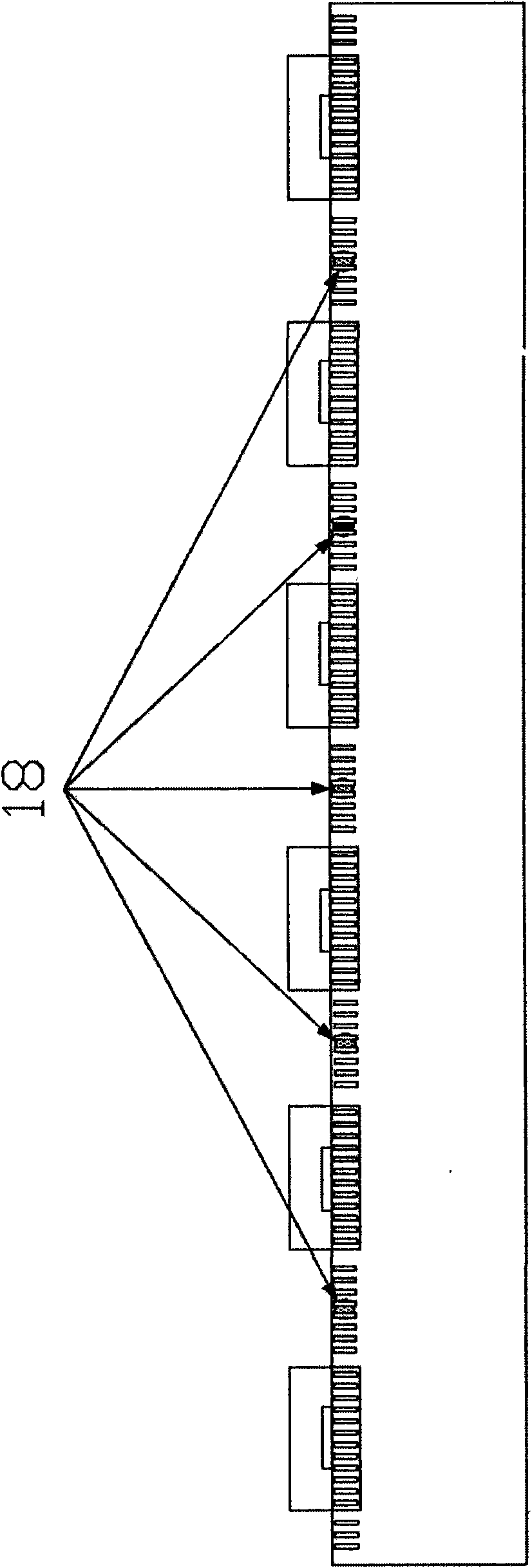
[0020] In order to save costs, the length of the drive circuit board has been shortened. Following the trend, the distance between the printed circuit board and the iron frame needs to be shortened, so the distance between the printed circuit board and the plastic frame is relatively shortened;

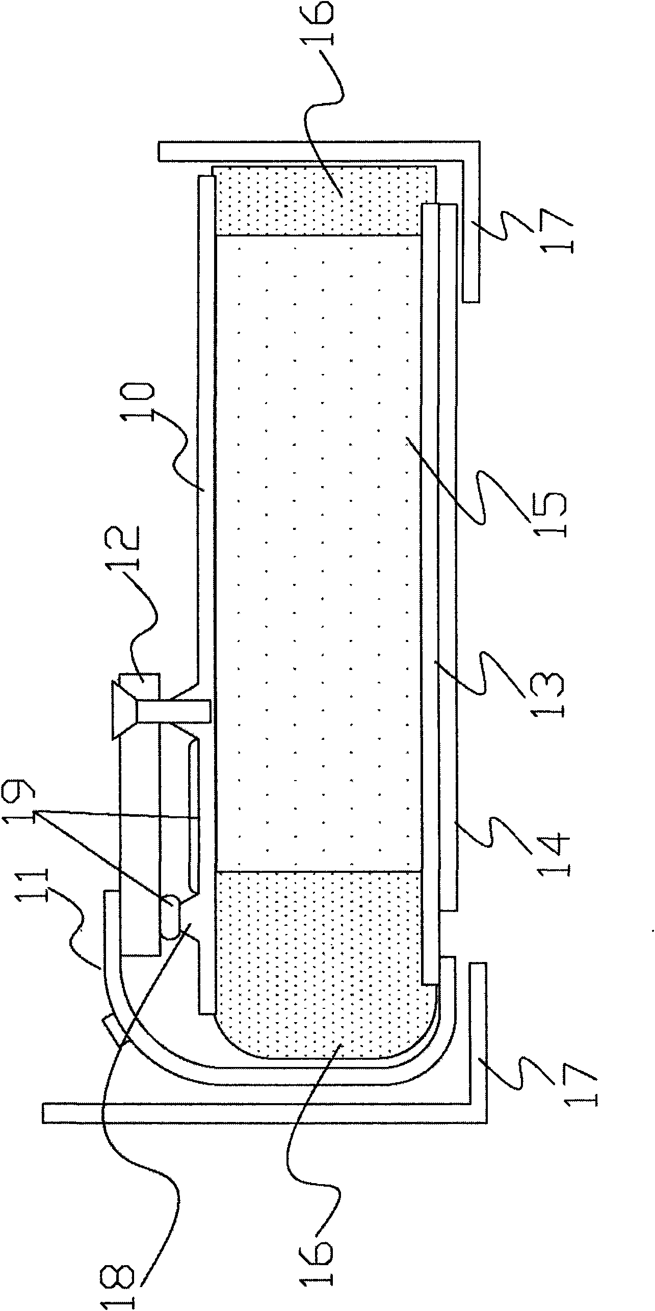
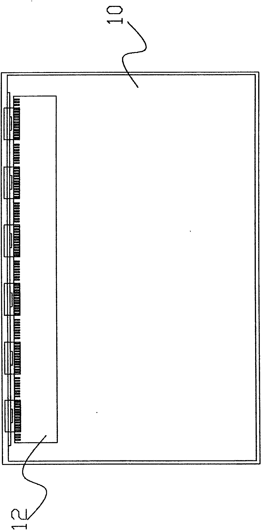
[0021] The present invention proposes a backplane structure of a backlight module, please refer to Figure 4 As shown, the backplane structure 20 of the backlight module includes a frame 21. In this embodiment, the frame 21 is an iron frame as an example for illustration; The back plate 22 has at least one through positioning hole 23 and at least one positioning portion 231, wherein the positioning hole 23 can be in the shape of a square or a circle, and this embodiment uses a circle as an example for illustration, and the positioning portion 231 is a screw hole; a drive circuit board 24, this drive circuit board 24 has an integrated circuit control chip (IC) 241 and a printed circuit...


PUM


Abstract

The invention mainly relates to a backlight module device, in particular to a backboard structure of a backlight module. The backboard structure comprises a framework, a backboard, a driving circuit board, a first fixing element and a second fixing element, wherein the backboard is arranged in the framework and provided with at least one penetrated positioning hole and one positioning part; the driving circuit board is provided with a fixing hole at a position opposite to the positioning part of the backboard; and the first fixing element and the second fixing element respectively correspond to the backboard, the positioning hole and the positioning part of the driving circuit board so as to ensure that the backboard and the driving circuit board are combined and fixed in the framework. The backboard structure can improve the insulating effect of the driving circuit board, reduce the occurrence frequency of short circuit of electronic elements and reduce the cost and assembly working hours.

Description

technical field [0001] The present invention mainly relates to a backlight module device, in particular to a backplane structure of the backlight module. Background technique [0002] Since the liquid crystal panel is not a self-illuminating display device, an external light source must be used to achieve the display effect. The general liquid crystal panel almost uses a backlight module, and the backlight module mainly provides a uniform and high-brightness light source for the liquid crystal panel. The basic principle is the Commonly used point or linear light sources are converted into high-brightness and uniform luminance surface light source products through simple and effective light. [0003] In recent years, with the progress of the flat-panel display industry and the improvement of LCD manufacturing technology, although the cost of flat-panel displays has been reduced, the profit of the product has also been reduced as the production technology matures and leads to ...

Claims


Application Information

Patent Timeline
Patent Type & Authority Applications(China)
IPC IPC(8): G02F1/13357G02F1/13F21V21/00G02F1/1335
Inventor 赖世道
Owner CENTURY DISPLAY (SHENZHEN) CO LTD
Why Eureka
Try Eureka