Positioning antenna for portable terminal and portable terminal thereof

A technology for positioning antennas and portable terminals, which is applied in the directions of antennas, resonant antennas, antenna supports/installation devices, etc., to achieve the effect of reducing impact and saving space

Active Publication Date: 2009-11-04
LENOVO (BEIJING) CO LTD
View PDF0 Cites 5 Cited by
  • Summary
  • Abstract
  • Description
  • Claims
  • Application Information

AI Technical Summary

Problems solved by technology

[0012] The purpose of the present invention is to provide a positioning antenna for a portable terminal and its portab

Method used


Image

  • Positioning antenna for portable terminal and portable terminal thereof
  • Positioning antenna for portable terminal and portable terminal thereof
  • Positioning antenna for portable terminal and portable terminal thereof

Examples


Embodiment Construction

[0043] In order to make the purpose, technical solutions and advantages of the embodiments of the present invention more clear, specific embodiments will be described in detail below with reference to the accompanying drawings.

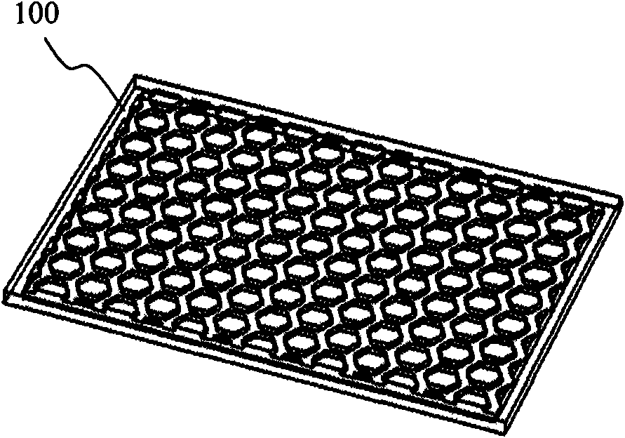
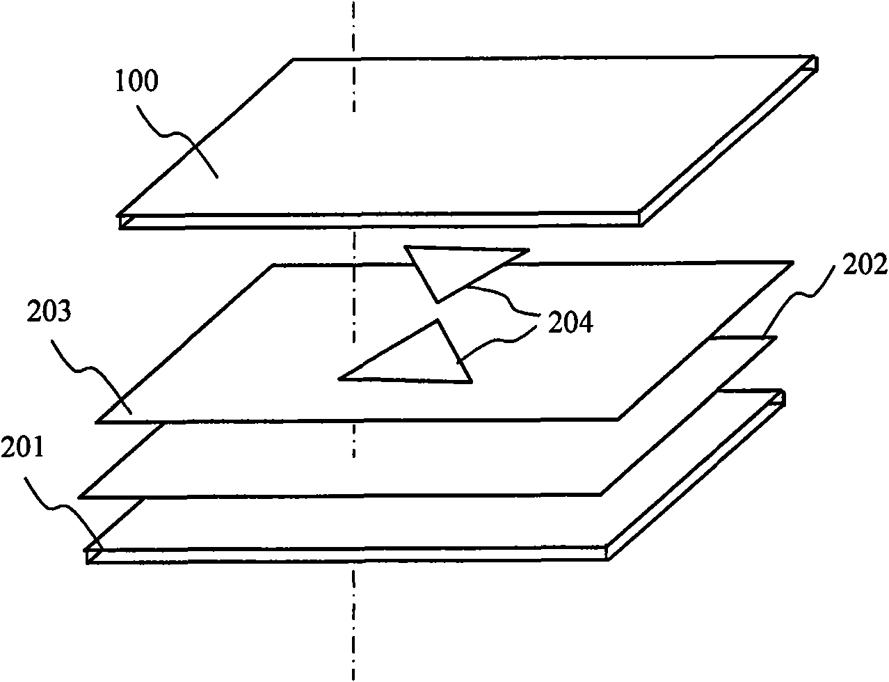
[0044] An embodiment of the present invention provides a frequency-selective ultra-thin high-gain reconfigurable positioning antenna for portable terminal positioning. Positioning antenna frequency selective surface structure view as figure 1 As shown, the positioning antenna includes: a frequency selective surface 100 with a first resonant frequency and a second resonant frequency, a flat (thickness is smaller than the length and width) microstrip antenna body (including figure 2 201-204 in ), disposed immediately below the frequency selective surface, having a first directivity pattern corresponding to the first resonant frequency and a second directivity pattern corresponding to the second resonant frequency.

[0045] figure 2The exploded struc...


PUM


Abstract

The invention provides a positioning antenna for a portable terminal and the portable terminal thereof. The positioning antenna comprises a frequency selective surface and a microstrip antenna main body, wherein the frequency selective surface is provided with first resonant frequency and second resonant frequency; and the microstrip antenna main body is arranged below the frequency selective surface and provided with first characteristic information corresponding to the antenna directivity of the first resonant frequency and second characteristic information corresponding to the antenna directivity of the second resonant frequency. The invention solves the technical problem that the positioning can only be realized under certain fixed attitude in the prior art. The antenna has a restructurable directional diagram, not only can form high directional gain but also can be restructured into omnidirectional gain, and can be effectively positioned under any satellite attitude.

Description

technical field [0001] The invention relates to the terminal antenna technology of a positioning system, in particular to a positioning antenna for a portable terminal and the portable terminal. Background technique [0002] Popularizing the global positioning system on notebook computers is a future market trend, and the global positioning system has high requirements on the polarization and pattern (characteristic information of the antenna directivity) of the terminal antenna. In particular, China's own Beidou positioning system has high requirements for terminal antenna gain. Even if a high-gain (40dB) low-noise amplifier is used, the antenna gain is still greater than 4dBi. On a notebook computer, the space available to install the antenna is limited, even the "microstrip positioning antenna" is still too large: about 50mm long, 50mm wide, and 3-5mm thick, and the satellite direction must be kept on a 50mm×50mm plane It is difficult to use conveniently within the norma...

Claims


Application Information

Patent Timeline
IPC IPC(8): H01Q1/22H01Q1/38H01Q13/08H01Q9/04H01P1/20
Inventor 颜罡张孝林崔斌智建军
Owner LENOVO (BEIJING) CO LTD
Why Eureka
Try Eureka