
Compensating charging method and circuit for electric automobile

A charging circuit and electric vehicle technology, applied in electric vehicles, battery circuit devices, circuit devices, etc., can solve the problem that the auxiliary battery cannot recover braking energy, etc., and achieve the effect of improving energy utilization

Inactive Publication Date: 2009-11-04
TIANJIN QINGYUAN ELECTRIC VEHICLE
View PDF0 Cites 16 Cited by
  • Summary
  • Abstract
  • Description
  • Claims
  • Application Information

AI Technical Summary

Problems solved by technology

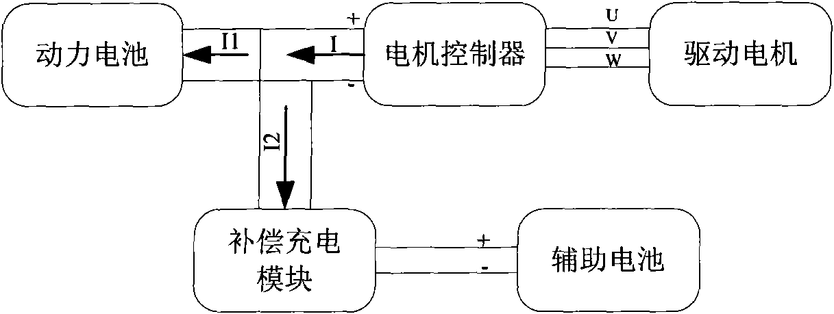
Since the output of the DC / DC module is a constant working voltage, generally 13.5V (for cars or mini cars) or 27V (for passenger cars), it can only provide floating charge for the auxiliary battery, so that the auxiliary battery is always fully charged or near full charge, so the figure 1 In the conventional braking energy regenerative charging topology shown, the auxiliary battery cannot recover braking energy

Method used


Image

  • Compensating charging method and circuit for electric automobile
  • Compensating charging method and circuit for electric automobile
  • Compensating charging method and circuit for electric automobile

Examples


Embodiment Construction

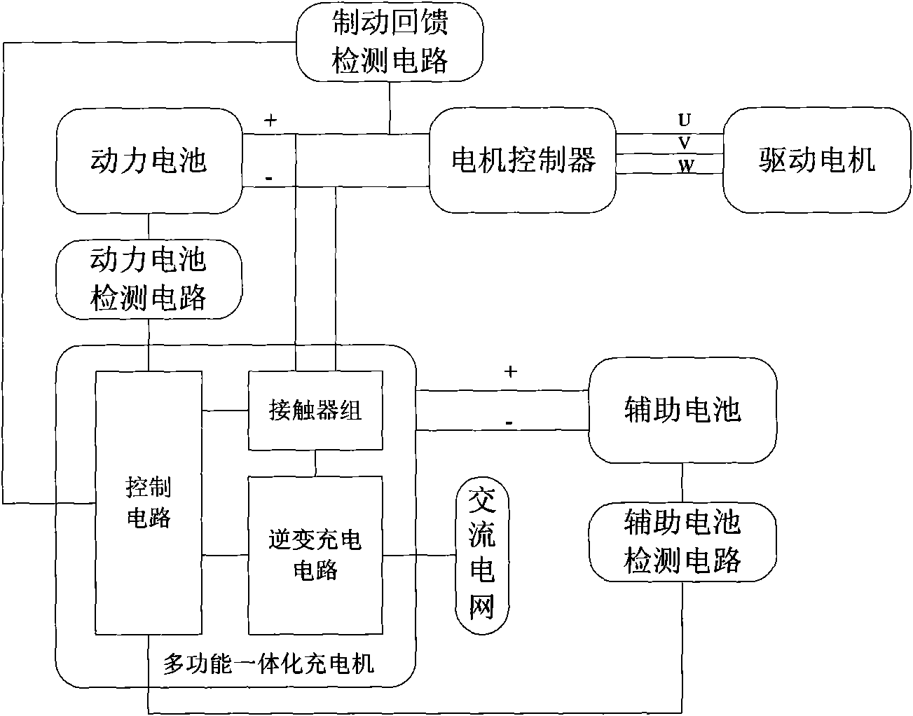
[0015] see figure 2 , figure 2 It is the basic principle block diagram of electric vehicle compensation charging. figure 2 Including power battery, motor controller, drive motor, compensation charging module, auxiliary battery, high-voltage DC bus, three-phase AC bus, low-voltage DC bus. The power battery, motor controller and compensation charging module are connected through a high-voltage DC bus, the motor controller is connected with the driving motor through a three-phase AC bus, and the compensation charging module is connected with the auxiliary battery through a low-voltage DC bus. The compensation charging module includes a monitoring circuit, a control circuit and a charging circuit inside.

[0016] When the electric vehicle brakes, figure 2 The electric energy generated by the driving motor in the battery enters the motor controller through the three-phase AC bus, and is converted into high-voltage DC, and then divided into two parts through the high-voltage ...


PUM


Abstract

The invention belongs to the technical field of electric automobile charging, and particularly relates to a compensating charge method. The method divides the braking feedback energy into two parts, one part of energy is used for charging an electrokinetic cell and is recycled, and the other part of energy is used for the compensating charging of an auxiliary cell by an inverter charging circuit and is recycled; and according to the test result carried out by a testing circuit to test whether the braking feedback energy, the rest energy of the auxiliary cell and the rest energy of the electrokinetic cell exist or not, the level of the braking feedback energy which is distributed into the auxiliary cell for the compensating charging thereof is controlled. The invention also provides a circuit for realizing the charging method. The invention makes up the disadvantage of the conventional mode of braking energy feedback charging that the braking energy can only be recycled by the electrokinetic cell, and improves the energy utility ratio of the electric automobile.

Description

technical field [0001] The invention belongs to the technical field of electric vehicle charging, and relates to a method for recovering braking energy from an auxiliary battery compensating a power battery. technical background [0002] The braking energy generated by traditional vehicles during the braking process is mainly converted into heat energy loss, while electric vehicles can drive the motor in reverse during the braking process to make it in the state of power generation, and convert the braking energy into electrical energy, which is fed back to the power Battery charging (referred to as "regenerative charging") stores the braking energy in the power battery, and when the electric vehicle is running, it is released from the power battery to drive the electric vehicle, so the recovery of braking energy can improve the energy utilization rate. It is one of the main reasons why electric vehicles can be more energy-efficient than conventional vehicles. [0003] fig...

Claims


Application Information

Patent Timeline
Patent Type & Authority Applications(China)
IPC IPC(8): H02J7/34H02J7/00
Inventor 宫学庚亓玉梅韩毅梁枫陶志军苟毅彤
Owner TIANJIN QINGYUAN ELECTRIC VEHICLE
Learn More