Automatic mortar spraying device for coating mortar for wall surface

A spraying device and mortar technology, which is applied in the direction of construction and building construction, can solve the problems of failure to realize automation, failure to meet energy saving requirements, and large amount of ash falling, so as to achieve fully automatic operation and controllable and adjustable mortar thickness , good adsorption effect

Inactive Publication Date: 2009-11-11
朱登仁
View PDF0 Cites 9 Cited by
  • Summary
  • Abstract
  • Description
  • Claims
  • Application Information

AI Technical Summary

Problems solved by technology

The defect of this kind of machinery is: when the ash hopper is running up and down, the mortar is attached to the wall in the gap between the ash hopper and the wall. There is almost no extrusion during this process, so the mortar has poor adhesion and is slightly thick. Some will fall; and it can only work in one direction, which does not meet the energy saving requirements
Both cannot realize the quantitative control of mortar, and cannot realize automatic control operations; the plastering adhesion is poor, and the amount of ash falls
Due to limited technical conditions, it cannot fully meet the construction requirements of the working surface, and a large amount of labor is required to complete the ash hanging operation on the working surface that the machine cannot complete. Therefore, the ash hanging process cannot be truly automated.
[0006] There are also some mechanical devices similar to the above-mentioned products, whose performance and technology are similar to the above-mentioned products, and cannot fully meet the requirements of hanging dust on the wall of the automatic external powder operation, and have not been promoted and applied in practice. The problem of hanging dust on the walls of the homework is still a top priority

Method used


Image

  • Automatic mortar spraying device for coating mortar for wall surface
  • Automatic mortar spraying device for coating mortar for wall surface
  • Automatic mortar spraying device for coating mortar for wall surface

Examples


Embodiment Construction

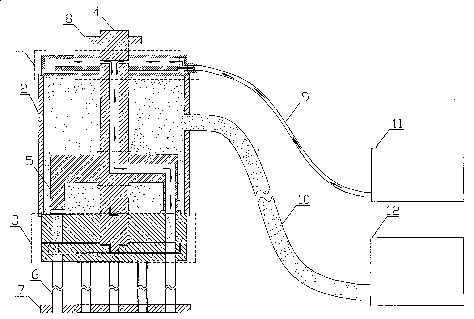
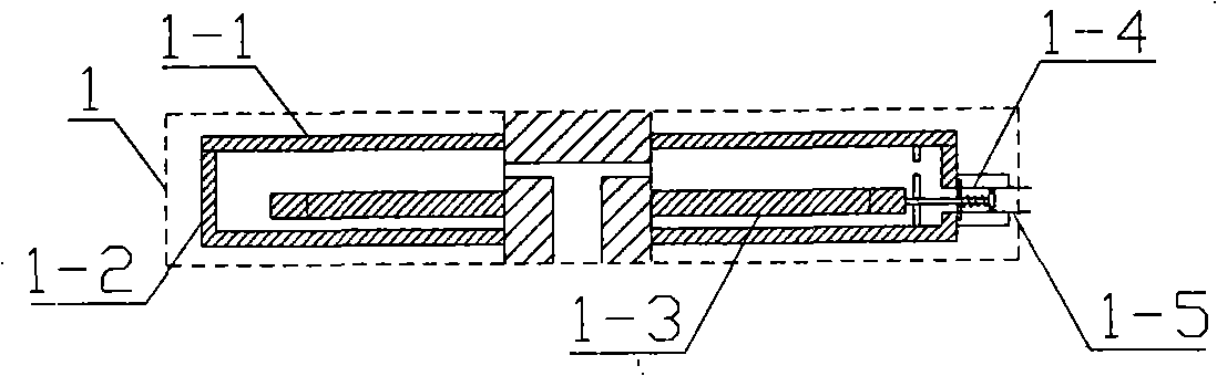
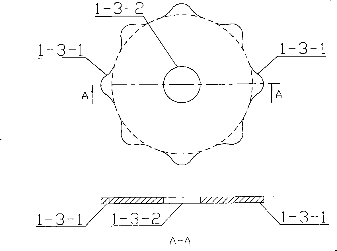
[0076] In actual manufacturing, the components of the high-pressure air chamber 1, the mortar box 2 and the slurry-distributing tray assembly 3 are all cast by foundry, and may also be made of steel pipes or steel plates. Central rotating shaft 4 adopts round steel to make. The joints between the central rotating shaft 4 and the high-pressure air chamber 1, the mortar box 2, and the porous slurry separator 3-1 are fixed by bearings, and the joints are sealed by sealing rings. Air inlets 1-5 and pulp inlets 2-2 are connected to conveying pipes with universal quick connectors in the industry for easy installation and disassembly. Intake check valve 1-4 can adopt mechanical valve, also can adopt electromagnetic valve, triggers its switch by multi-point distributing cam 1-3. The number of the edge protrusions 1-3-1 of the multi-point gas distribution cam 1-3 is the same as the number of the grout holes 3-1-1 and the mortar injection pipes 6, and the distribution on the disk surfa...


PUM


Abstract

The invention relates to an automatic mortar spraying device for coating mortar for a wall surface, which utilizes compressed air to uniformly spraying mortar to building surface. The main structure comprises a high-pressure air chamber 1, a mortar box 2, a mortar separation disc composite member 3, a central rotation shaft 4, a mortar pressing and air spraying integrated head 5, a mortar spraying pipe 6, a mortar spraying head 7 and a drive wheel 8. When the central rotation shaft rotates, a multiple-point atmolysis cam, the mortar pressing and air spraying integrated head and a mortar control disc synchronously rotate. When an air spraying nozzle and a mortar through hole aim at a mortar separation hole of the multiple-hole mortar separation disc, air inlet holding valves are turned on at the same time, high-pressure air fast goes into the air inlet holding valves and presses the mortar in the mortar separation hole out, and the mortar reaches the mortar spraying head along a spraying pipe and is sprayed out. The invention utilizes controllable high pressure airflow to uniformly spray mortar with quantified volume to the building surface, the spraying of the mortar is uniform, the adsorption effect of the wall face is good, the thickness of the mortar is controllable and adjustable, and the invention can realize fully automated operation by combining with an automated bearing platform.

Description

technical field [0001] The invention relates to a mechanical device, in particular to an automatic mortar spraying device for wall hanging ash which uses compressed air to uniformly spray mortar onto the surface of a building. Background technique [0002] At present, in the process of building construction, the automation of external powder coating of building walls has always been an insurmountable technical problem. In the process of external powder, how to evenly apply the mortar and closely adhere to the wall (commonly known as hanging ash) is the first step, and it is also one of the most difficult technologies to solve. In this field, there are also some explorers who have researched and developed some mechanical products and equipment to solve the problem of powder hanging on the outside, but because of various deficiencies and defects, these machinery and equipment have not been widely used. [0003] One of them is a vertical lifting plastering machine. The basic p...

Claims


Application Information

Patent Timeline
Patent Type & Authority Applications(China)
IPC IPC(8): E04F21/12
Inventor 朱登仁
Owner 朱登仁
Why Eureka
Try Eureka