

Powder metallurgy compressor unloading shaft sleeve and method for preparing same
A powder metallurgy and compressor technology, applied in the field of powder metallurgy compressor unloading bushing and its preparation, achieves the effects of high yield, few steps and simple operation
- Summary
- Abstract
- Description
- Claims
- Application Information
AI Technical Summary
Problems solved by technology
Method used
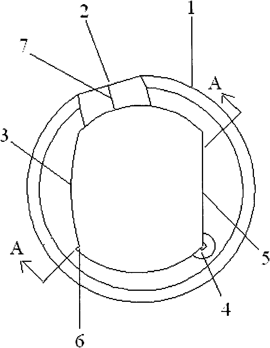
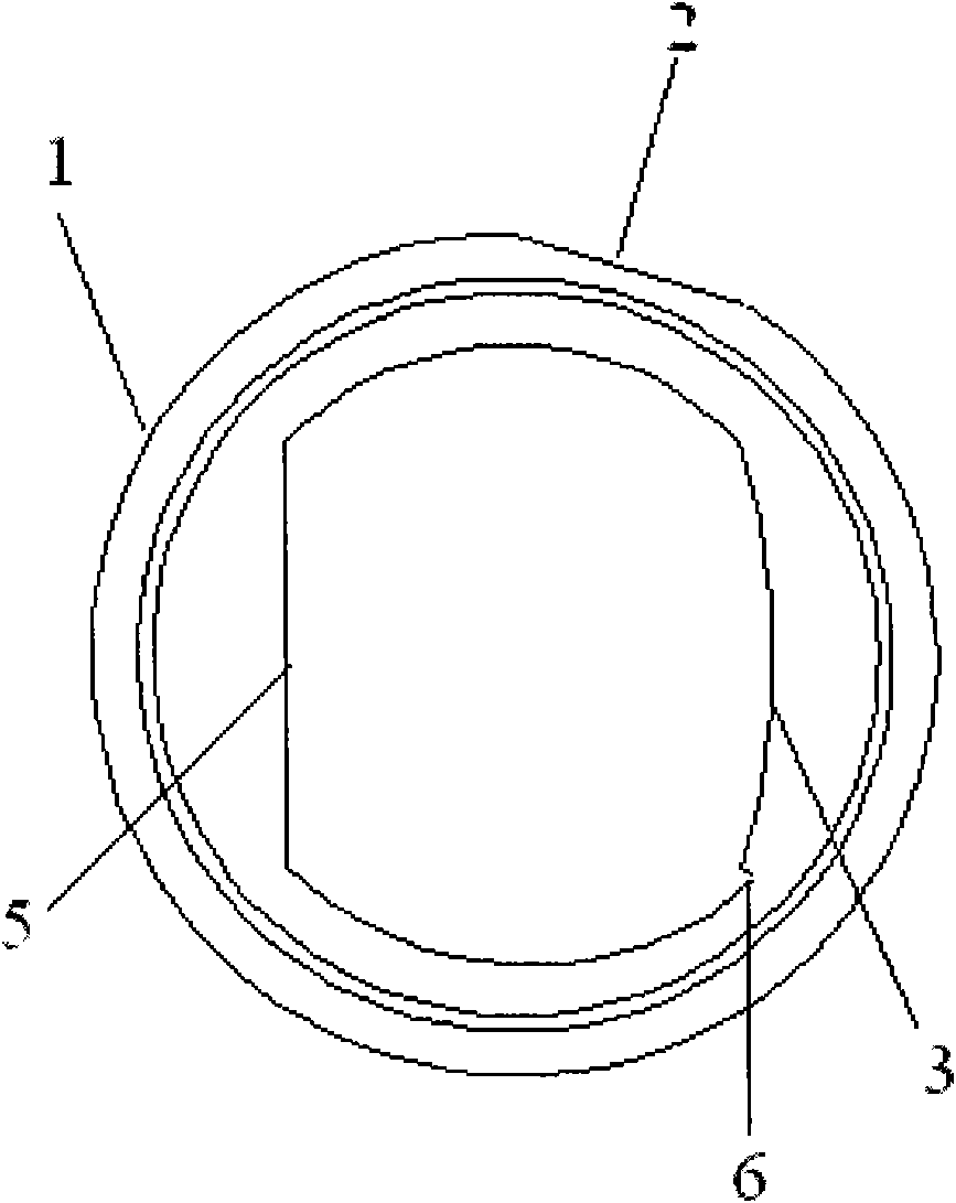
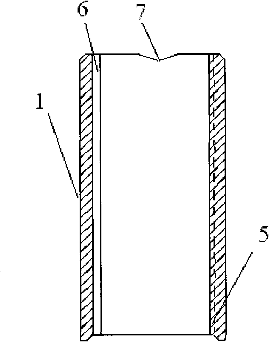
Image

Examples
Embodiment 1
[0029] After mixing Fe powder, C powder and Mo powder evenly, put them into a molding machine for molding; the parts by weight of each component are: C: 0.30, Mo: 1.0, and the rest is Fe powder; the temperature is controlled at 850°C, and pre-sintered ; followed by shaping; temperature control at 1050°C, and then sintering; heat treatment, after 8 hours, cryogenic treatment; vacuum oil immersion and telecentric separation in sequence, that is, the powder metallurgy compressor unloading sleeve is prepared.
[0030] After testing, the average hardness of the shaft sleeve is HRC≥38, the minimum hardness value is HRC≥35, and the residual austenite structure of the shaft sleeve is 15%, which fully meets the requirements for use. After the durability test, they all meet the life test requirements of the product.
Embodiment 2
[0032] After mixing Cu powder, Fe powder, C powder and Mo powder evenly, put them into a molding machine for molding; the parts by weight of each component are: Cu: 3.0, C: 1.0, Mo: 2.0, and the rest is Fe powder; Control temperature at 940°C, pre-sintering; then shaping; temperature control at 1100°C, then sintering; heat treatment, 6 hours later, cryogenic treatment; vacuum oil immersion and telecentric separation in sequence to prepare powder metallurgy compressor unloading shaft set.
[0033] After testing, the average hardness of the shaft sleeve is HRC ≥ 38, the minimum hardness value is HRC ≥ 35, and the residual austenite structure of the shaft sleeve is 10%, which fully meets the requirements for use. After the durability test, they all meet the life test requirements of the product.
Embodiment 3
[0035] After mixing Cu powder, Fe powder, C powder and Mo powder evenly, put them into a molding machine for molding; the parts by weight of each component are: Cu: 1.0, C: 0.50, Mo: 1.5, and the rest is Fe powder; Control the temperature at 890°C, pre-sintering; then carry out shaping; control the temperature at 1120°C, and then sinter; conduct heat treatment, and after 2 hours, carry out cryogenic treatment; carry out vacuum oil immersion and telecentric separation in sequence, that is, the powder metallurgy compressor unloading shaft is prepared set.
[0036] After testing, the average hardness of the shaft sleeve is HRC ≥ 38, the minimum hardness value is HRC ≥ 35, and the residual austenite structure of the shaft sleeve is 5%, which fully meets the requirements for use. After the durability test, they all meet the life test requirements of the product.
PUM
 Abstract
Description
Claims
Application Information