Device for transmitting luminous energy by utilizing paraboloidal mirror

A technology of parabolic mirror and conveying device, which is applied in the direction of using feedback control, optics, installation, etc., and can solve problems such as the inability to manufacture high-power laser transmitters

Inactive Publication Date: 2009-11-11
黄建文
View PDF7 Cites 29 Cited by
  • Summary
  • Abstract
  • Description
  • Claims
  • Application Information

AI Technical Summary

Problems solved by technology

However, lasers are man-made and expensive light sources, and until now it has not been possible to manufacture powerful laser emitters

Method used


Image

  • Device for transmitting luminous energy by utilizing paraboloidal mirror
  • Device for transmitting luminous energy by utilizing paraboloidal mirror
  • Device for transmitting luminous energy by utilizing paraboloidal mirror

Examples


Embodiment 1

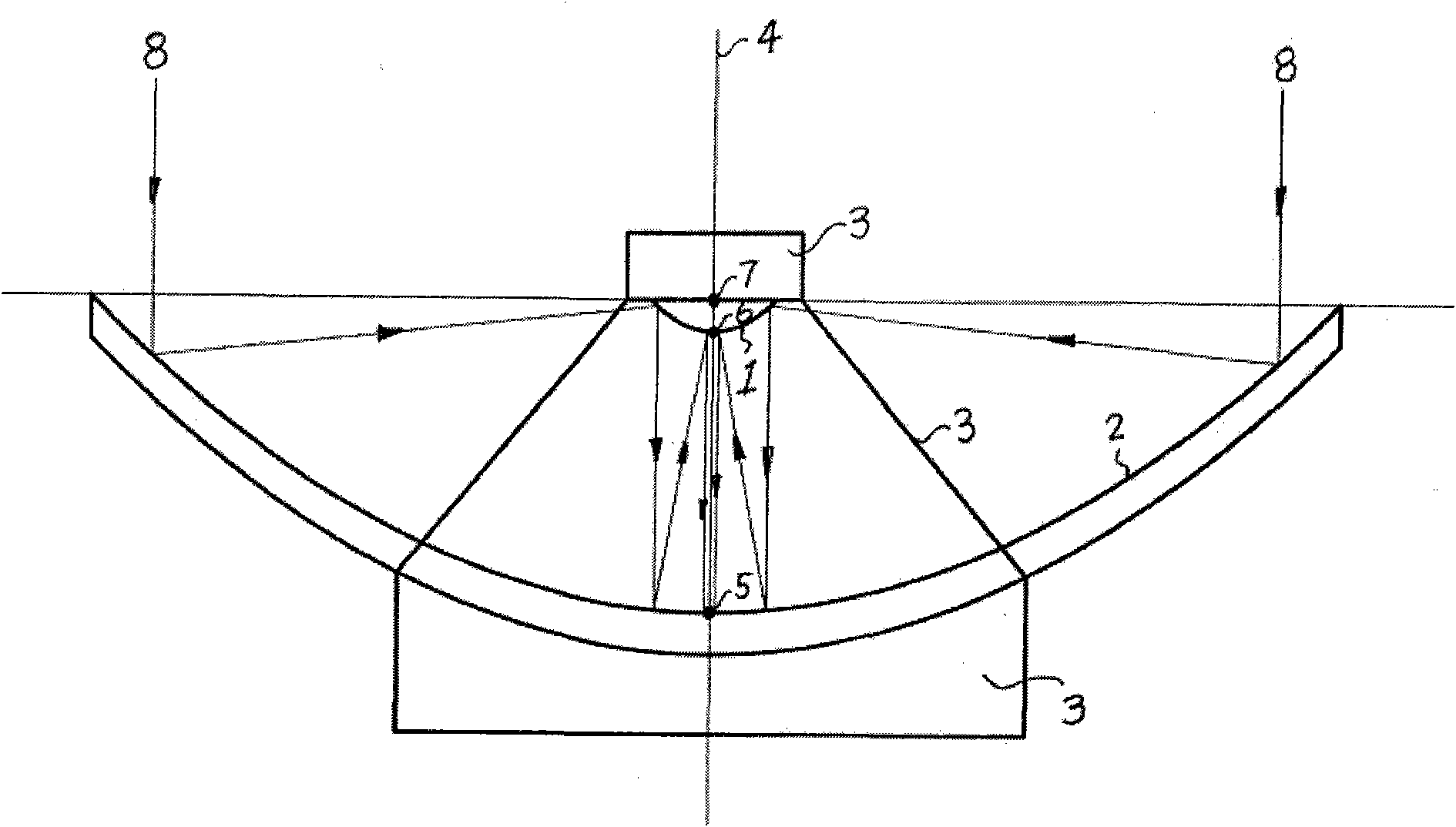
[0070] figure 1 It is a structural diagram of the first embodiment of the device for transmitting light energy by using a parabolic mirror in the present invention, and it is also a basic structural diagram of the present invention. As shown in the figure, the device for transmitting light energy using a parabolic mirror includes: at least one parabolic convex reflector 1 , at least one parabolic concave reflector 2 and a supporting device 3 . The convex surface of the parabolic convex reflector 1 is a parabolic reflective surface. The concave surface of the parabolic concave reflector 2 is a parabolic reflective surface. The reflective surfaces of the parabolic convex reflector 1 and the parabolic concave reflector 2 are arranged oppositely, and the parabolic shapes of the two reflective surfaces are similar. The so-called similar shape is that the curvatures of the corresponding points of the two parabolas are equal, and the geometric dimensions are in equal proportions. ...

Embodiment 2

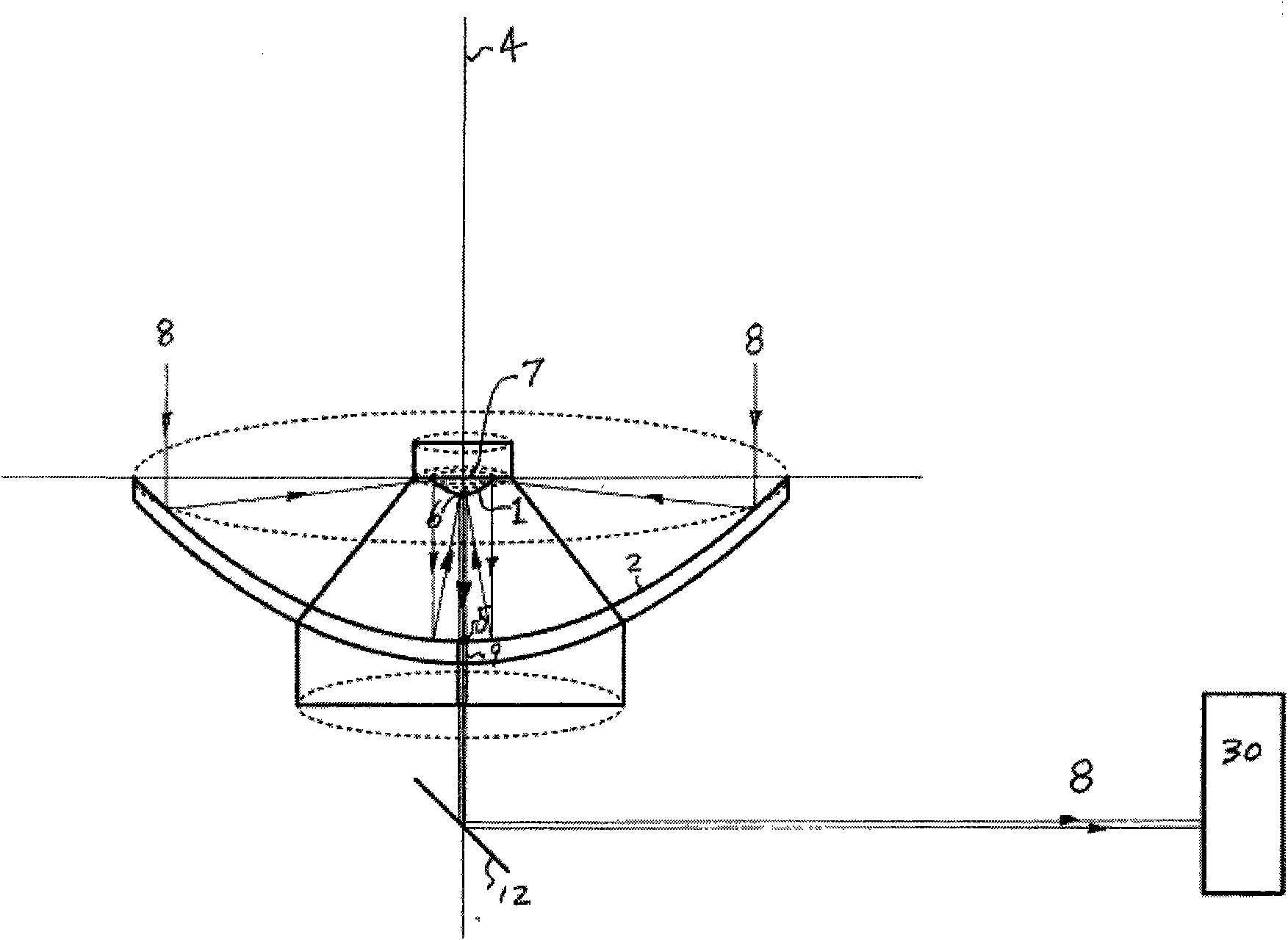
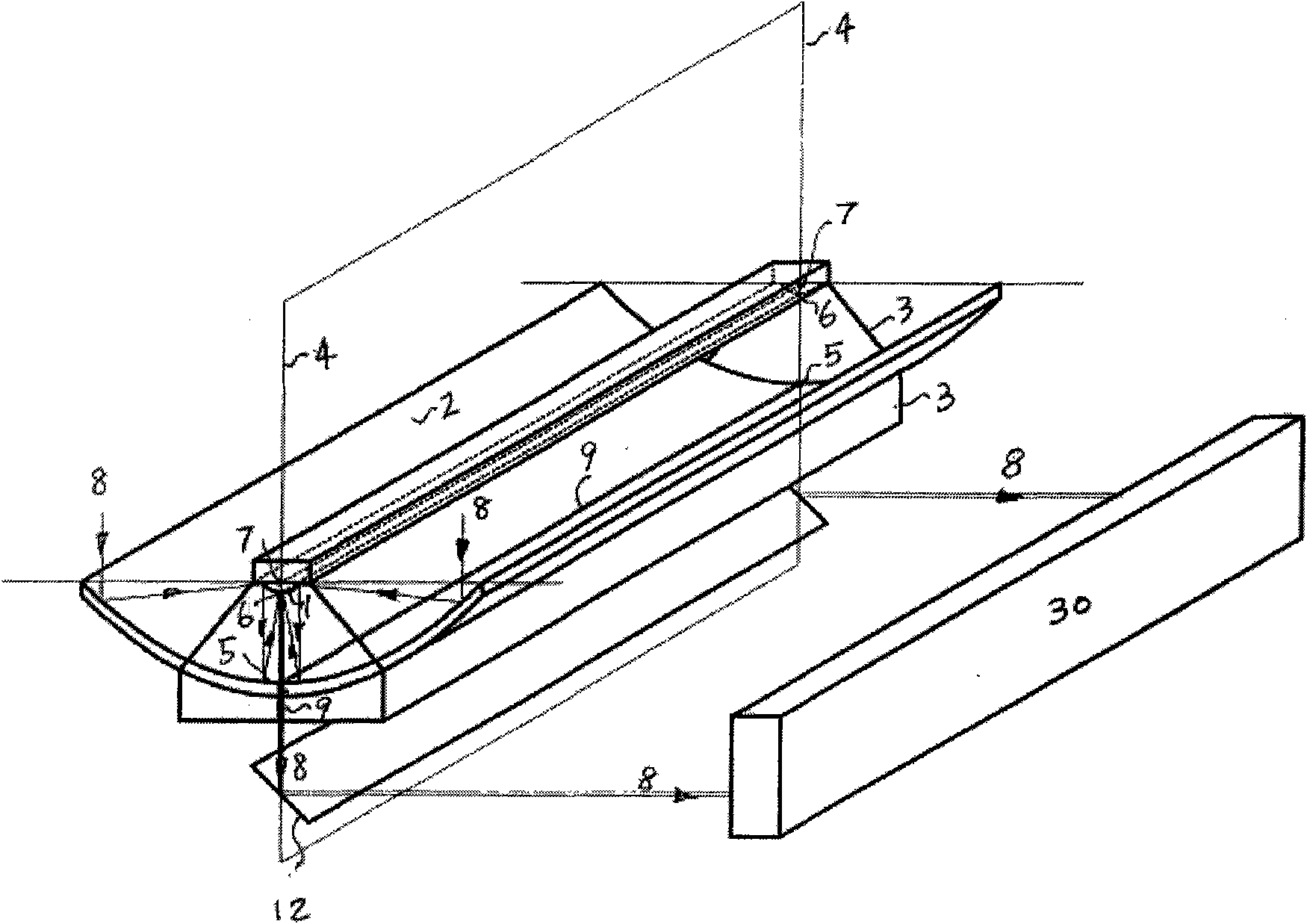
[0076] Such as figure 2As shown, the second embodiment is based on the first embodiment, and further defines that the parabolic reflective surfaces of the parabolic convex reflector 1 and the parabolic concave reflector 2 are both parabolic surfaces of revolution. The foci of the two parabolic surfaces of revolution coincide with the focal point 7 . The coincident focal point 7 is on the same straight line as the vertices 5 and 6 of the two parabolic surfaces of revolution, and this straight line is the common axis 4 of the two parabolic surfaces of revolution.

Embodiment 3

[0078] Such as figure 2 As shown, the third embodiment is based on the second embodiment, wherein a hole 9 is opened at the apex 5 of the parabolic concave reflector 2 , and the center of the hole 9 is on the common axis 4 . In this way, the converged parallel light beam 8 can be irradiated through the circular aperture 9 .


PUM


Abstract

The invention provides a device for transmitting luminous energy by utilizing a paraboloidal mirror. The device comprises at least one parabola convex reflector and at least one parabola concave reflector. The convex surface of the parabola convex reflector is a parabolic reflecting surface, and the concave surface of the parabola concave reflector is a parabolic reflecting surface. The reflecting surfaces of the parabola convex reflector and the parabola concave reflector are oppositely arranged, and parabola shapes of the two reflecting surfaces are similar to each other. The geometric dimension of the reflecting surface of the parabola concave reflector is larger than that of the reflecting surface of the parabola convex reflector. The axes of the reflecting surfaces of the two parabola reflectors are overlapped at a common axis, and the focuses of the reflecting surfaces are overlapped at a common focus. The device takes advantage of the special ray reflecting characteristics of the paraboloidal mirror to effectively gather or disperse parallel rays entering the device, thereby realizing multiple different actual applications.

Description

technical field [0001] The invention relates to a device that uses a parabolic mirror to transmit light energy. The device uses the special light reflection characteristics of the parabolic mirror to effectively converge or disperse the parallel light rays incident on the device, thereby realizing various practical applications. It belongs to optical equipment technology field. Background technique [0002] Light is a kind of electromagnetic radiation, which can be regarded as light waves or photons; it can be divided into visible light and invisible light based on human visual ability. All high-frequency electromagnetic radiation has the same physical characteristics as visible light, and can be regarded as a light source. Sunlight, moonlight, starlight, artificial laser light, other artificial light sources, visible light, invisible light, and electromagnetic radiation are all light sources. At present, the technology of converging light sources is mainly divided into th...

Claims


Application Information

Patent Timeline
Patent Type & Authority Applications(China)
IPC IPC(8): G02B17/06G05D3/12G02B7/182G02B7/198G02B6/00
CPCG02B17/061G02B17/0684G02B19/0042G02B19/0076G02B19/0023F24S23/74F24S23/79Y02E10/40
Inventor 黄建文
Owner 黄建文
Why Eureka
Try Eureka