Broadband ceiling type omni antenna

An omnidirectional antenna and ceiling-mounted technology, which is applied in antennas, antenna supports/mounting devices, and structural forms of radiation elements, can solve problems such as the out-of-roundness of the radiation pattern on the horizontal plane, and achieve simple structure and smooth frequency response characteristics , The effect of convenient production and installation

Inactive Publication Date: 2009-11-11
GUANGDONG SHENGLU TELECOMM TECH
View PDF1 Cites 5 Cited by
  • Summary
  • Abstract
  • Description
  • Claims
  • Application Information

AI Technical Summary

Problems solved by technology

Although it has advantages such as frequency bandwidth, its radiation pattern on the horizontal plane is not round, and its electrical performance indicators such as low-frequency band gain and third-order intermodulation need to be further improved.

Method used


Image

  • Broadband ceiling type omni antenna
  • Broadband ceiling type omni antenna
  • Broadband ceiling type omni antenna

Examples


Embodiment Construction

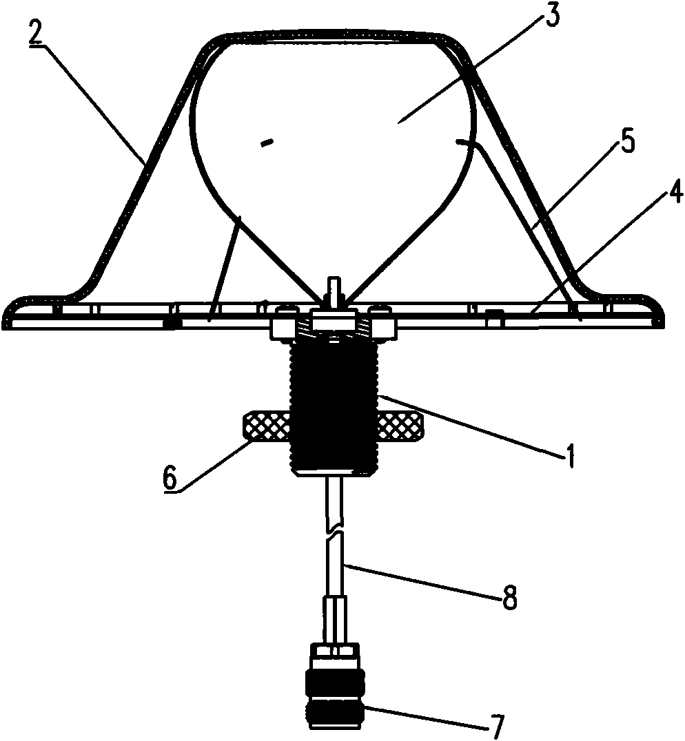
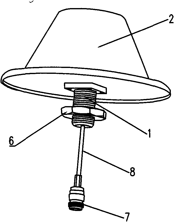
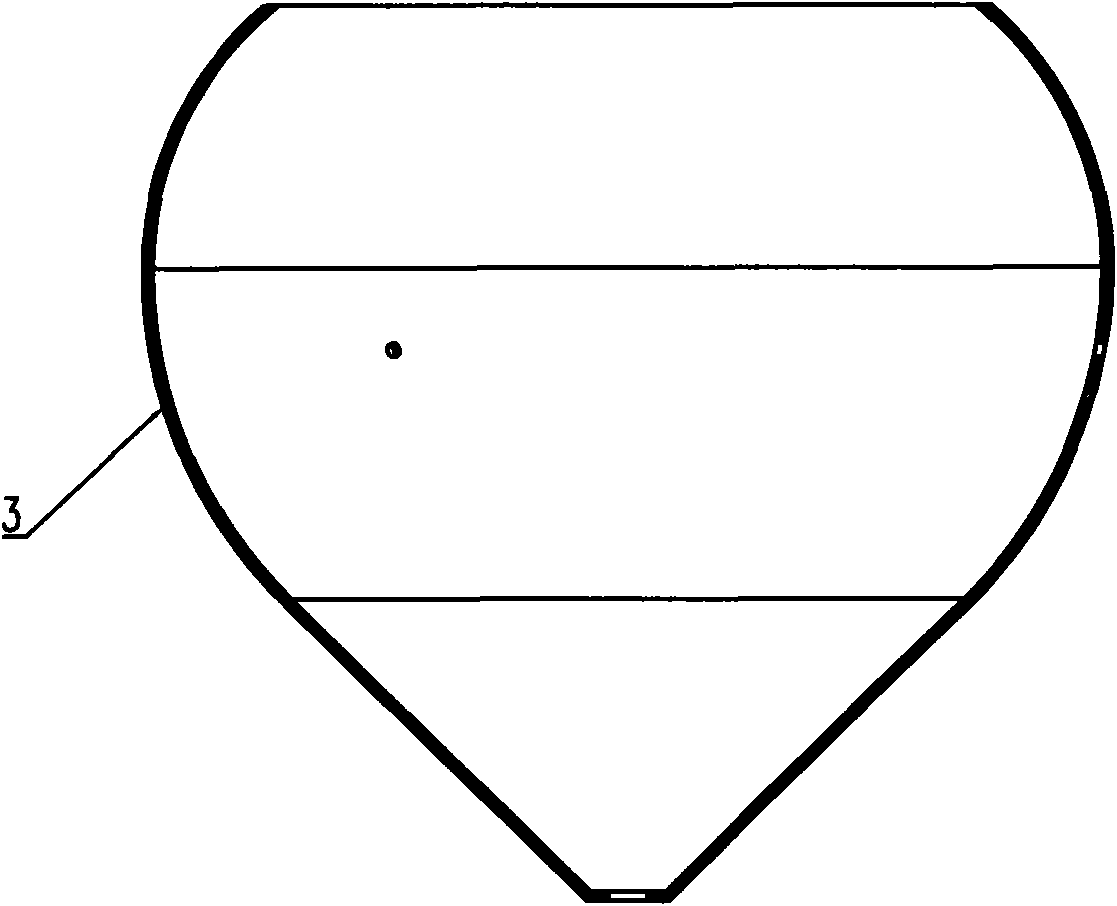
[0032] Such as Figure 1 to Figure 13 As shown, the broadband ceiling-mounted omnidirectional antenna of the present invention is mainly composed of a coaxial connector A1, a radome 2, a radiation oscillator 3, and a reflector 4. The radiation oscillator 3 is made of a metal material and is integrally formed by a special stamping and stretching process. Or it can be stamped and formed in two parts, the upper part is in the shape of an open sphere, and the lower part is in the shape of a cone. The upper part and the lower part are connected as one by riveting. characteristics, so that the voltage standing wave ratio of the entire frequency band meets the design requirements (<1.4), and achieves a good broadband purpose. In this embodiment, a hole is opened at the center of the cone of the radiating vibrator 3, and a fastening nut coaxial with the vibrator is installed in it, and the coaxial connector A1 is installed on the reflector through the hole, and is screwed with the fas...


PUM


Abstract

The invention discloses a broadband ceiling type omni antenna, which comprises a coaxial connector, an antenna dome, a radiation oscillator, a short-circuit line (wafer) and a baffle board, wherein the radiation oscillator is fixed on the baffle board and has the shape of an opening conisphere or an opening elliptic conisphere. The broadband ceiling type omni antenna is characterized in that two parts of the radiation oscillator are subjected to seamless transition and tangentally connected with each other into a whole; the metallic short-circuit line (wafer) is arranged between the baffle board and the radiation oscillator; and one end of the short-circuit line (wafer) is welded with the radiation oscillator and the other end of the short-circuit line (wafer) is riveted or welded on the same side face of the baffle board and the radiation oscillator. The antenna has the advantages of simple structure, stable performance, superior electrical performance index, easy and simple assembly and beautiful appearance, covers the communication modes of frequency ranges such as CDMA800, GSM, DCS, PCS, WCDMA, TD-SCDMA, WiFi and WiMax, has wide application scope, and can achieve the aim of saving resources.

Description

technical field [0001] The invention relates to the technical field of antennas, in particular to a ceiling-mounted omnidirectional antenna. Background technique [0002] At present, the ceiling-mounted omnidirectional antennas in the prior art generally cover relatively few frequency bands, have complex structures, poor out-of-roundness and third-order intermodulation indicators of the horizontal plane radiation pattern, and are not conducive to mass production. For example, the application number is 200620056145, and the name of the invention is broadband ceiling omnidirectional antenna. It includes a radiator, a bottom plate and a radome. The radiator is installed on the bottom plate. The radiator includes an upper part and a lower part. The upper part is cylindrical and the lower part is inverted Conical type, the upper part and the lower part are connected as a whole, the bottom of the radiator is connected with a metal cylinder, and a through wire hole is arranged in t...

Claims


Application Information

Patent Timeline
Patent Type & Authority Applications(China)
IPC IPC(8): H01Q1/12H01Q1/42H01Q1/36H01Q13/02H01Q15/14
Inventor 黄绍明卓贵清
Owner GUANGDONG SHENGLU TELECOMM TECH
Why Eureka
Try Eureka