Radio-frequency push-pull power amplifier

A power amplifier, radio frequency technology, applied in push-pull amplifiers, high-frequency amplifiers, phase splitters, etc., can solve the problem of deteriorating the signal amplitude balance and phase inversion performance of the balanced port of the balun impedance converter, affecting the RF push-pull power amplifier. Technical characteristics, incomplete symmetry of the structure, etc., to achieve the effect of facilitating mass production, improving performance, and having a symmetrical and compact structure

Active Publication Date: 2009-11-11
SUNWAVE COMM
View PDF0 Cites 21 Cited by
  • Summary
  • Abstract
  • Description
  • Claims
  • Application Information

AI Technical Summary

Problems solved by technology

But the structure of this balun impedance converter is not completely symmetrical, the U-shaped coaxial cable section 316 in the direction of the unbalanced input port is not parallel to the printed circuit board, and its midpoint is difficult to determine, which will deteriorate the balun. The impedance converter balances the amplitude balance and phase inversion performance of the port signal, thus affecting the technical characteristics of the RF push-pull power amplifier; the coaxial cable of this balun impedance converter has two sections that need to be stripped of the outer conductor, and then the two sections are tightly wound. circle, difficult to process, poor reproducibility
[0009] The RF push-pull power amplifier based on the existing balun impedance converter has problems such as large size, difficult processing, and poor reproducibility. The electrical characteristics of the RF push-pull power amplifier need to be further improved.

Method used


Image

  • Radio-frequency push-pull power amplifier
  • Radio-frequency push-pull power amplifier
  • Radio-frequency push-pull power amplifier

Examples


Embodiment Construction

[0031] A kind of radio frequency push-pull power amplifier that the present invention proposes is described in detail as follows in conjunction with accompanying drawing and embodiment:

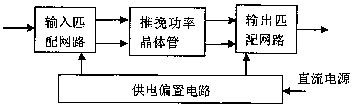
[0032] The radio frequency push-pull power amplifier that the present invention proposes, as Figure 4 , Figure 8 As shown, it includes an input matching network 1, a push-pull RF power transistor 2, an output matching network 3 and a power supply bias circuit 4. Among them, the push-pull power transistor is connected to the input matching network and the output matching network respectively, and the power supply bias circuit supplies power to the push-pull power transistor through the input matching network and the output matching network connected to it; the power supply bias circuit is connected to the external DC power supply connected; the input matching network, output matching network and power supply bias circuit are made on a printed circuit board, and the printed circuit board and...


PUM


Abstract

The invention relates to a radio-frequency push-pull power amplifier, belonging to the technical field of radio-frequency circuit. The radio-frequency push-pull power amplifier comprises the following four parts of a push-pull power transistor, an input matching network, an output matching network and a power supply bias circuit; the output matching network comprises an output balun impedance converter and an output matching circuit; the output balun impedance converter comprises a U-shaped coaxial cable and two identical straight coaxial cables that are overlapped in parallel and arranged on a printing circuit board horizontally, and two insulated leads; the two leads connect the internal conductor of the U-shaped coaxial cable with the internal conductor of the straight coaxial cable so as to form one conductor; the external conductors of two ends of the U-shaped coaxial cable are two low-resistance balance ports; the internal conductor of one end of the two straight coaxial cables is grounded and the other end thereof is a high-resistance unbalanced port; and the middle point of the external conductor of the U-shaped coaxial cable is connected with a direct current power and is grounded by a capacitance radio frequency. The radio-frequency push-pull power amplifier has symmetric structures, small space occupying, convenient processing and good repeatability, and greatly improves the electrical performance.

Description

technical field [0001] The invention belongs to the technical field of radio frequency circuits, in particular to the design of radio frequency push-pull power amplifiers. Background technique [0002] RF push-pull power amplifiers are widely used in communication, broadcasting, radar, industrial processing, medical equipment and scientific research and other fields. RF high power amplifiers generally adopt the push-pull form. The RF push-pull power amplifier is composed of four parts: a push-pull power transistor, an input matching network connected to the push-pull power transistor, an output matching network and a power supply bias circuit, such as figure 1 As shown, the push-pull power transistor is directly installed on the surface of the metal heat sink, the input matching network, output matching network and power supply bias circuit are fabricated on the printed circuit board, and the power supply bias circuit is connected to the external DC power supply. These prin...

Claims


Application Information

Patent Timeline
Patent Type & Authority Applications(China)
IPC IPC(8): H03F3/19H03F3/26
Inventor 陈兆武陈正伟蔡晓亚蔡长发
Owner SUNWAVE COMM
Why Eureka
Try Eureka