
Electronic apparatus

A technology for electronic equipment and electrical signals, applied in branch equipment, telephone communication, electrical components, etc., can solve the problems of bending and twisting parts, operation restrictions, and reduced durability, so as to suppress mechanical stress and noise, and enhance durability. Effects of Sexuality and Reliability

Inactive Publication Date: 2009-11-18
SONY CORP
View PDF7 Cites 2 Cited by
  • Summary
  • Abstract
  • Description
  • Claims
  • Application Information

AI Technical Summary

Problems solved by technology

[0006] (1) With the portable terminals disclosed in Patent Documents 1 and 2, the cables need to be folded, twisted, and / or stretched / contracted in the rotation and sliding of the housing, causing a problem that stress is imposed on the bent portion and the twisted portion. Heavier loads and therefore reduced durability
So it's to be expected that reduced durability is going to be a big problem
[0007] (2) The method of sliding the contact point in the slidable portable terminal has such a problem that a change in mechanical load and electrical signal noise are generated due to a change in contact pressure
[0008] (3) With the optical connector disclosed in Patent Document 3, since the communication is performed by engaging the male bracket with the female bracket, there is an operation restriction
Therefore, for example, it is difficult to perform data transmission in a state where the above-mentioned case rotates and slides

Method used


Image

  • Electronic apparatus
  • Electronic apparatus
  • Electronic apparatus

Examples


no. 1 example

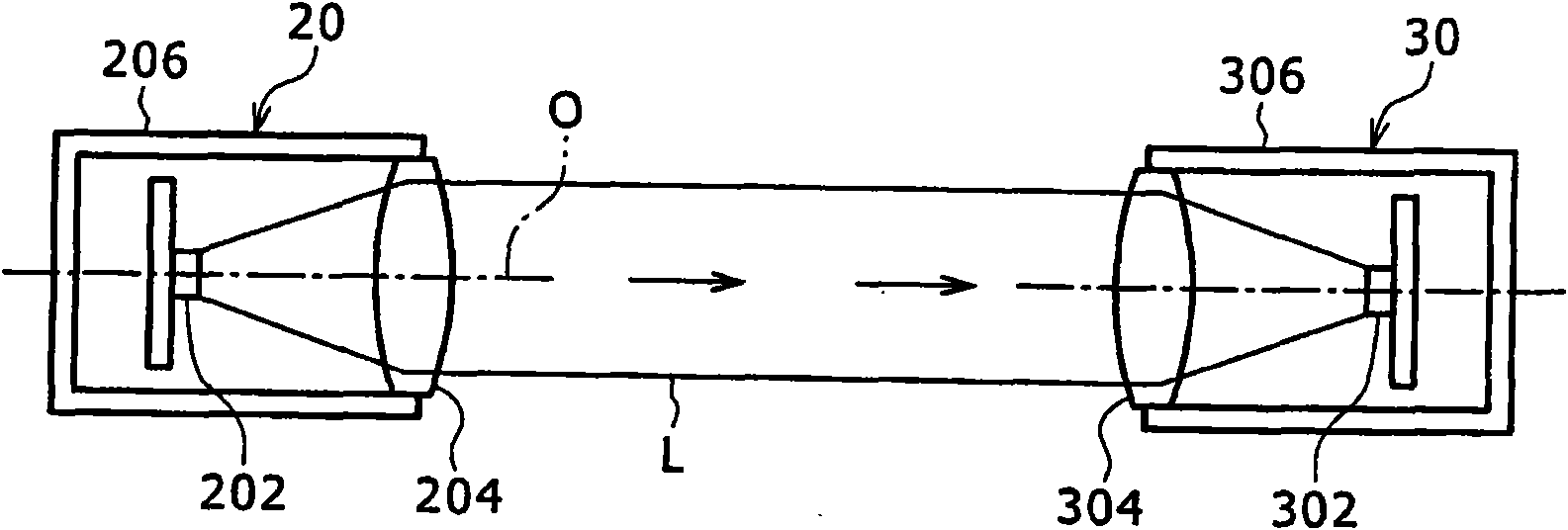
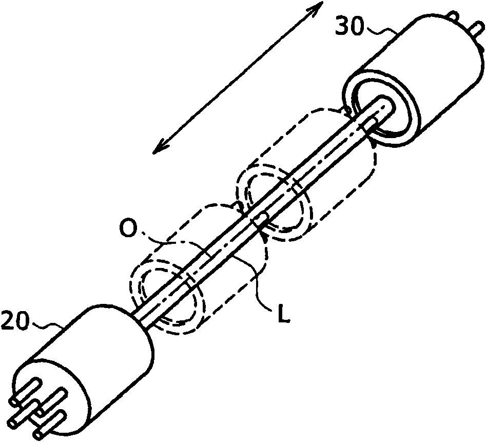
[0035] Embodiments of the present invention will be described below with reference to the drawings. The basic operation of the optical space transmission according to the embodiment of the present invention will first be described below. In the optical space transmission, a transmitter optical subassembly (TOSA) 20 as an example of an optical transmission module, and a receiver optical subassembly (ROSA) 30 as an example of an optical reception module are used.

[0036] figure 1 is a schematic diagram showing the configuration of TOSA 20 and ROSA 30 . The TOSA 20 is a compact optical device for light transmission, and includes a laser diode 202 , a collimator lens 204 and a support 206 . The support 206 is, for example, a cylindrical member, and supports the laser diode 202 and the collimator lens 204 . The laser diode 202 emits laser light L having a predetermined wavelength. The collimator lens 204 is arranged on the optical axis O of the laser diode 202, and converts th...

no. 2 example

[0075] Another embodiment of the present invention will be described below with reference to the accompanying drawings. For the basic operations for optical space transmission and the like, the same components as those described for the first embodiment will be assigned the same reference numerals and symbols, and detailed description thereof will be omitted.

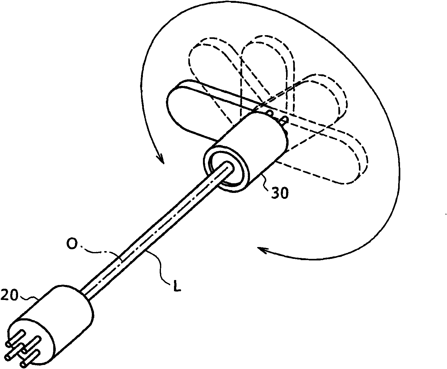
[0076] Figure 21 The schematic diagram of shows the configuration of the monitoring device 100 according to the second embodiment of the present invention. The monitoring device 100 is attached to a ceiling or the like in an indoor space through an attachment 104 and is used to image and record a specific shooting range in a store, an outdoor space, or the like. The swivel joint unit 106 is arranged between the monitoring device 100 and the attachment 104 . The rotary hinge unit 106 is rotatably driven by a driving unit (not shown, such as a motor), so that the monitor device 100 rotates around the optical axis O. As...


PUM


Abstract

The invention discloses an electronic apparatus including a light transmitting module configured to convert an electric signal into an optical signal and emit light; a light receiving module configured to receive the light emitted from the light transmitting module and convert the optical signal into an electric signal; and a mover unit configured to cause at least one of the light transmitting module and the light receiving module to carry out linear movement along an optical axis of the light emitted from the light transmitting module and / or rotation about the optical axis.

Description

technical field [0001] The present invention relates to electronic equipment. Specifically, the electronic device includes a motion unit that causes at least one of the light transmitting module and the light receiving module to perform a linear motion along the optical axis of the light and / or perform a rotation around the optical axis, and the electronic device linearly Data transmission is performed between the light transmitting module and the light receiving module through optical space transmission during motion and rotation. Background technique [0002] In recent years, as portable terminals such as cellular phones, portable terminals having various structures such as foldable (rotatable) structures and slidable structures have been put into use. In the case of connecting components (circuit boards) capable of performing rotation, linear movement, etc. to each other by signal lines, for example, using flexible cables and harnesses and sliding contact points, these c...

Claims


Application Information

Patent Timeline
Patent Type & Authority Applications(China)
IPC IPC(8): H04M1/02H04B10/00H04B10/11H04B10/114H04B10/80
CPCH04B10/801H04M1/0235
Inventor 町田祐一
Owner SONY CORP
Learn More