Radiation system and lithographic apparatus

A radiation system and radiation beam technology, applied in microlithography exposure equipment, X-ray equipment, optomechanical equipment, etc., can solve the problems of component failure, large debris, and lack of cooling in the source system

Inactive Publication Date: 2009-11-18
ASML NETHERLANDS BV
View PDF4 Cites 3 Cited by
  • Summary
  • Abstract
  • Description
  • Claims
  • Application Information

AI Technical Summary

Problems solved by technology

However, generally an increase in the radiation output and / or repetition rate of the discharge source leads to greater fragmentation due to the higher temperatures reached and the consequent thermal load on the components
In some cases, components of the source system fail because they are not cooled adequately

Method used


Image

  • Radiation system and lithographic apparatus
  • Radiation system and lithographic apparatus
  • Radiation system and lithographic apparatus

Examples


Embodiment Construction

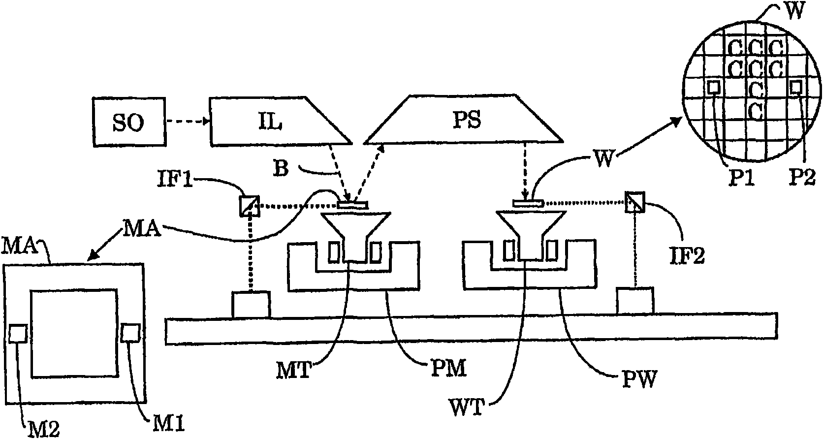
[0026] figure 1 A lithographic apparatus according to one embodiment of the invention is schematically shown. The lithographic apparatus comprises: an illumination system (illuminator) IL configured to condition a radiation beam B (e.g., ultraviolet (UV), or extreme ultraviolet (EUV) radiation); a support structure (e.g., a mask table) MT, It is configured to support a patterning device (such as a mask) MA and is connected to a first positioning device PM configured to precisely position the patterning device according to determined parameters; a substrate table (such as a wafer table) WT is configured to for holding a substrate (e.g. a resist-coated wafer) W and is connected to a second positioning device PW configured to precisely position the substrate according to determined parameters; and a projection system (e.g. refractive or reflective A projection lens system) PS configured to project the pattern imparted to the radiation beam B by the patterning device MA onto a ta...


PUM


Abstract

The invention relates to a radiation system for generating electromagnetic radiation. The radiation system includes a pair of electrodes constructed and arranged to generate plasma of a first substance and a pinch in the plasma. The radiation system also includes a plasma recombination surface that is arranged proximate to the pinch, and is configured to neutralize a plurality of plasma particles.

Description

technical field [0001] The invention relates to a radiation system, a lithographic apparatus comprising the radiation system, and a method for improving the repetition rate of the radiation system. Background technique [0002] A lithographic apparatus is a machine that applies a desired pattern to a substrate, usually a target portion of the substrate. For example, lithographic equipment may be used in the manufacture of integrated circuits (ICs). In this case, a patterning device, alternatively referred to as a mask or reticle, may be used to generate the circuit pattern to be formed on the individual layers of the IC. The pattern can be transferred onto a target portion (eg, comprising a portion, one or more dies) on a substrate (eg, a silicon wafer). Typically, the pattern is transferred by imaging the pattern onto a layer of radiation sensitive material (resist) provided on the substrate. Typically, a single substrate will contain a network of adjacent target portion...

Claims


Application Information

Patent Timeline
Patent Type & Authority Applications(China)
IPC IPC(8): H05G2/00G03F7/20
CPCB82Y10/00G03F7/70033H05G2/003H05G2/005H05G2/00G03F7/20
Inventor M·M·J·W·范赫彭V·Y·班尼恩V·V·伊凡诺夫K·N·科什烈夫D·J·W·科伦德尔
Owner ASML NETHERLANDS BV
Why Eureka
Try Eureka