

Driving device for controlled displaceable carriages
Patent Information
- Authority / Receiving Office
- CN · China
- Patent Type
- Applications(China)
- Current Assignee / Owner
- SCHAEFFLER TECH AG & CO KG
- Publication Date
- 2009-11-25
- Estimated Expiration
- Not applicable · inactive patent
Smart Images
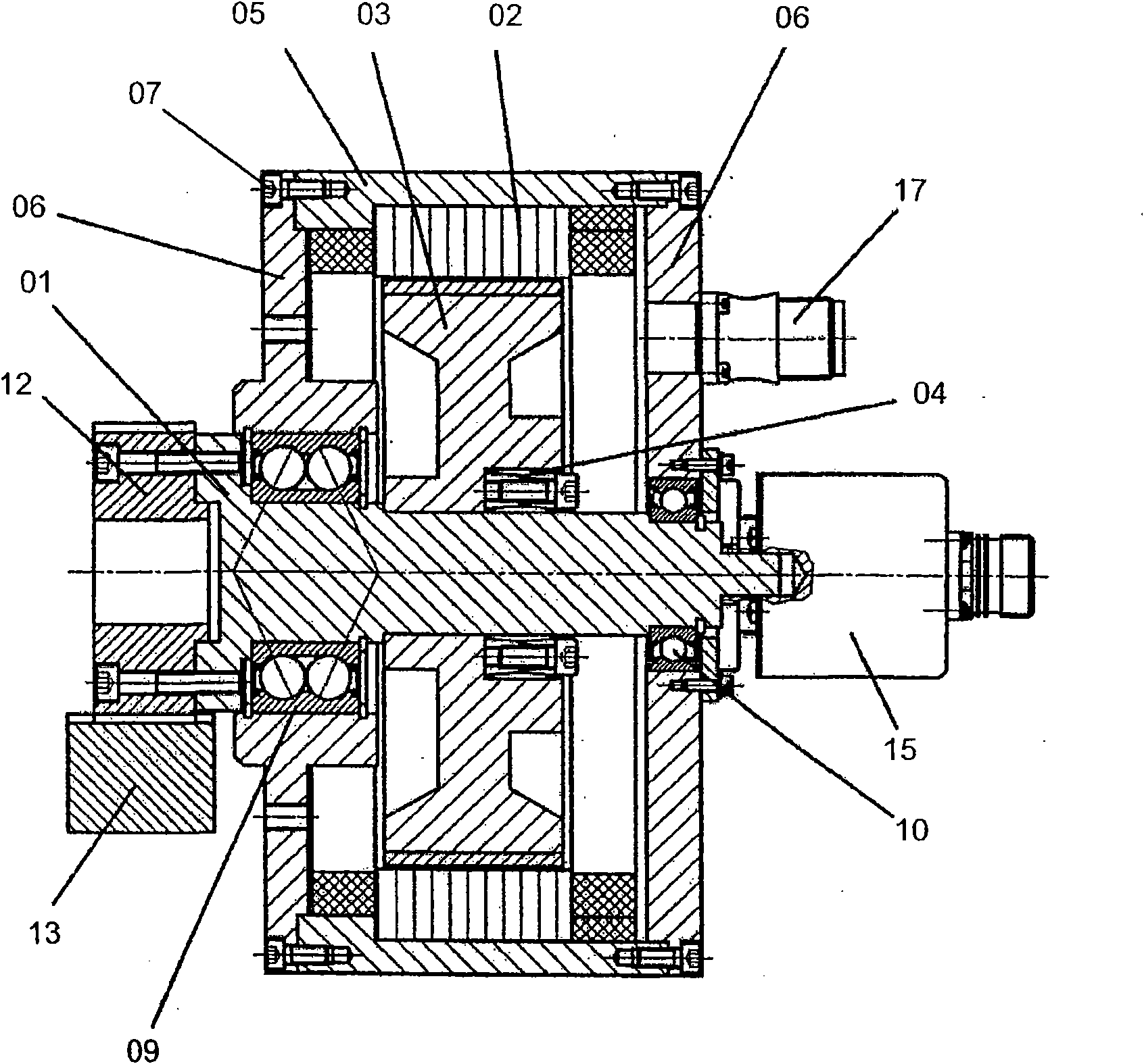
Figure 1
Abstract
Description
technical field
[0001] The invention relates to a drive for a machine tool for a controllably movable slide relative to the machine bed according to the preamble of appended claim 1 . Background technique
[0002] Generic drives are used, for example, on tool and other production machines with long linearly guided axes or slides which are moved in a controlled manner.
[0003] Linear axes, with which long and mechanically rigid axes can be realized, are currently usually driven by means of trapezoidal, spherical or roller screw drives. However, since there are often no hollow-shaft motors available, the spindle or the spindle nut and the electric servomotor have to be coupled by means of toothed belts. For reasons of power matching, a front-mounted transmission is generally required.
[0004] The disadvantage of these solutions is that these systems are structurally complex and expensive to acquire due to the large number of components required (spindle, spindle nut, tooth...