Water-wheel type pulse pump and water turbine generator for same

A technology of turbo generator and pulse pump, which is applied in the direction of hydroelectric power generation, impact engine, engine components, etc., can solve disadvantages and other problems, and achieve the effects of easy maintenance, saving capital investment, and improving air pollution

Inactive Publication Date: 2009-11-25
陈绍勇 +1
View PDF0 Cites 3 Cited by
  • Summary
  • Abstract
  • Description
  • Claims
  • Application Information

AI Technical Summary

Problems solved by technology

because it is at a disadvantage in

Method used


Image

  • Water-wheel type pulse pump and water turbine generator for same
  • Water-wheel type pulse pump and water turbine generator for same
  • Water-wheel type pulse pump and water turbine generator for same

Examples


Embodiment 1

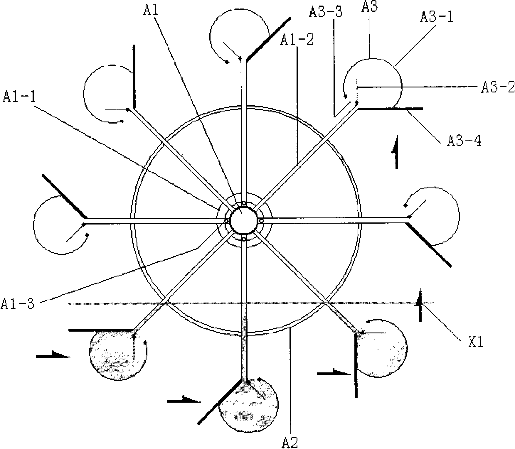
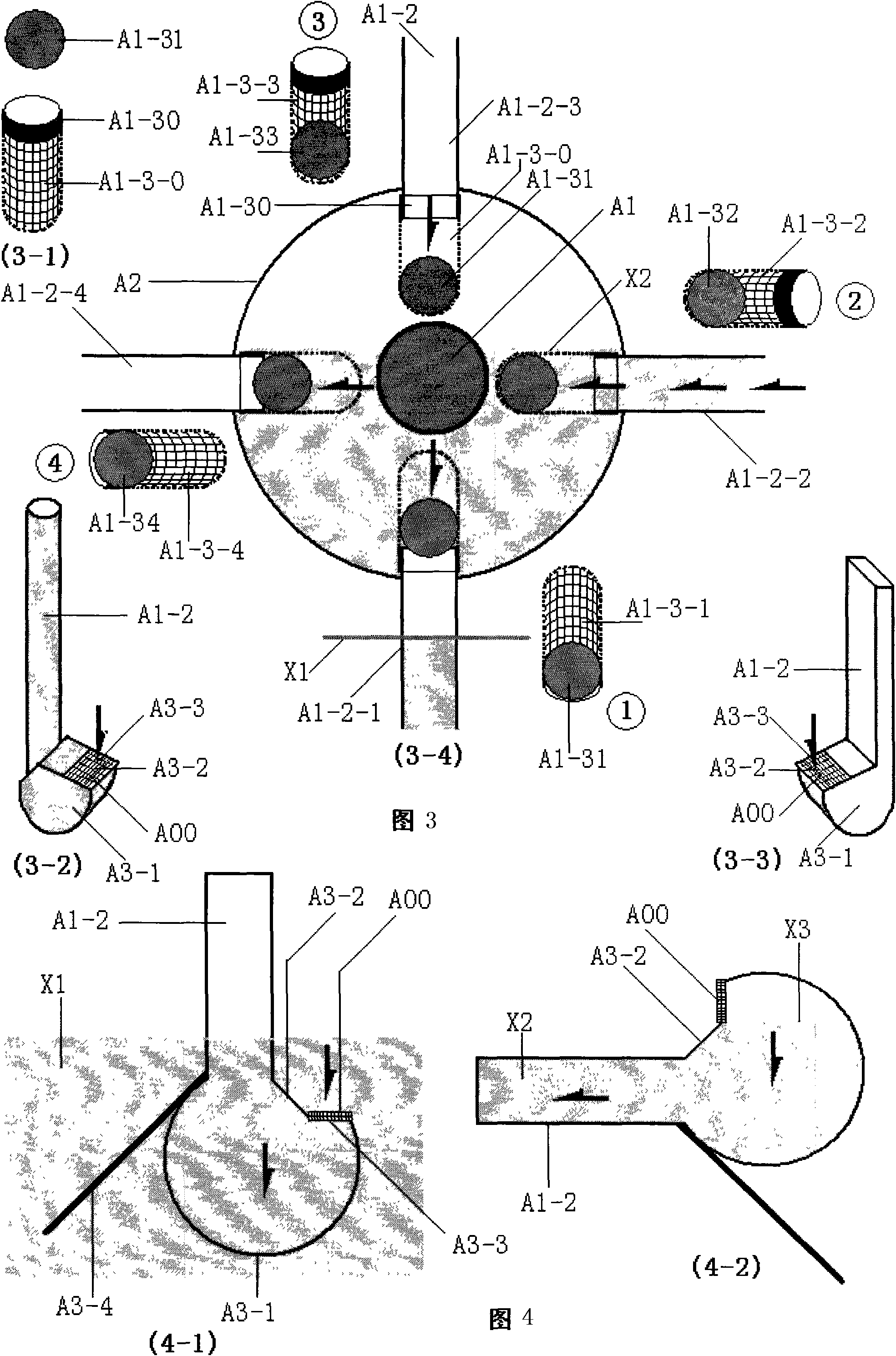
[0039] exist Figure 1 Middle: Side view of the water wheel of the ball valve water wheel pulse pump

[0040] In the figure: (A1) main output pipe of pump water, (A1-1) water valve lumen, (A1-2) pump water pipe, (A1-3) ball valve, (A3) water inlet scoop, (A3-1) water Scoop, (A3-2) water retaining tongue plate, (A3-3) water inlet, (A00) guard net cover, (A3-4) water flow push plate.

[0041] In the figure: the (A1-1) water valve lumen is connected outside the (A1) pump water main output pipe; the (A1-2) pump water pipe is connected outside the (A1-1) water valve lumen; -2) The connection between the pump water pipe and the (A1-1) water valve lumen is connected to the (A1-3) ball valve; the lower end of the (A1-2) pump water pipe is connected to the (A2) fixed ring; in (A1-2) The front end of the pump pipe is connected to the (A3) water inlet scoop; the (A3-1) water scoop is connected to the (A3-2) water retaining flap and the (A3-3) water inlet, and on the (A3-3) water inlet ...

Embodiment 2

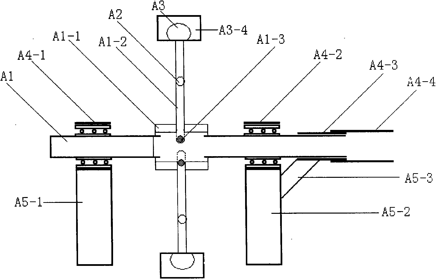
[0058] exist Figure five and Figure six Middle: Sectional diagram of vane valve waterwheel pulse pump

[0059] In the figure: (A1) main output pipe of pump water, (A1-1) water valve lumen, (A1-2) pump water pipe, (K1-1), (K1-2), (K1-3), (K1 -4) Valve vane, (K2-1), (K2-2), (K2-3), (K2-4) vane shaft, (K3-1), (K3-2), (K3-3), (K3-4) angle buckle, (A3) water inlet scoop, (A3-1) water scoop, (A3-2) water retaining tongue, (A3-3) water inlet, (A00) guard net cover, (A3 -4) water flow push plate, (A4-1) front bearing, (A4-2) rear bearing, (A4-3) sealing shaft sleeve, (A4-4) water pipe, (A5-1) front bracket, (A5 -2) Rear bracket, (A5-3) support bracket, (X1) running water, (X2) water surface inside the pump tube, (Z1) water flow direction, (Z2-1) (Z2-2) water ladle rotation direction.

[0060] In the figure: (A1) the pump water main output pipe is connected with the (A1-1) water valve lumen; the (A1-1) water valve lumen is connected with the (A1-2) pump water pipe; in (A1- 2) Th...

Embodiment 3

[0065] exist Figure 9 Middle: Cross-section diagram of water turbine generator

[0066] In the figure: (W) water turbine, (W1) turbine, (W2) turbine shaft, (W3) turbine upper bearing, (W4) gear, (W5) turbine lower bearing, (W6) transmission gear set, (L) set Water pan, (L1) Vertical side of pan, (L2) Connecting column, (L3) Return water collection pipe, (M1) Generator, (M2) Generator shaft, (M3) Generator shaft gear, (M4) Output source line, (M5) power switch box, (N) frame, (N1) upper connection side frame for generator, (N2) lower connection side frame for water turbine, (N3) base side frame, (N4) wheels.

[0067] In the figure: the (N4) wheel is connected under the (N3) base side frame of the (N) frame; the (M1) generator connected with the (M5) power switch box and the (M4) output source line is connected above; (M1) The (M2) generator shaft connected to the generator is connected to the (M3) generator shaft gear on the side frame connected to the (N1) generator; the (M...


PUM


Abstract

The invention relates to a water-wheel type pulse pump and a water turbine generator for the same. The invention comprises the water-wheel type pulse pump and the water turbine generator for the water-wheel type pulse pump. One or a group of generators can generate power of 10 to 50 kilowatts, 100 to 500 kilowatts or 1 to 10 megawatts. The invention can enable a small amount of original water flow in rivulets and channels to be merged into a large amount of water flow to be used for power generation. The water-wheel type pulse pump and the water turbine generator for the water-wheel type pulse pump can be installed in rivulets or channels having permanent water flow without building water retaining dams, changing the original structure and influencing the growing environment of organisms in the sea or river water. If a plurality of water-wheel type pulse pumps and water turbine generators for the water-wheel type pulse pumps are built along coastal areas and rivers in China, the generated energy is further larger than that of the prior various power plants and is enough to meet the requirement for electric energy at present and in the future in China. All thermal power plants, oil fired power plants and nuclear power plants can be eliminated, a large amount of coal and oil can be saved, and a large amount of fund investment can be saved. The water-wheel type pulse pump and the water turbine generator for the water-wheel type pulse pump are useful renewable energy resources for development of irrigational energy resources at present and in the future in China, and are used for providing a strategic decision for solving the energy crisis all over the world.

Description

Technical field: [0001] The development and utilization of renewable energy from oceans, rivers or canals. Background technique: [0002] Apart from the sun, the largest energy resource on the earth probably belongs to the sea. The sea accounts for 60% of the total area of ​​the earth, and the turbulent ocean has earth-shaking power. How to obtain it to replace more polluting mineral energy sources, such as coal, oil, etc., has become the pursuit of many scientific and technological authors day and night. 60% of the Earth's surface is covered by oceans. Therefore, the ocean is becoming a potential energy source that is still under development. [0003] We can harness the energy of oceans, rivers or canals, the greatest untapped source of energy on the planet. Plus, it's clean and recyclable. However, how to effectively convert the energy of oceans, rivers or canals into usable energy has been an unsolved problem for decades. [0004] If you can have 0.1% of ocean energy...

Claims


Application Information

Patent Timeline
IPC IPC(8): F03B13/00F03B1/00
CPCY02E10/223Y02E10/20
Inventor 陈绍勇
Owner 陈绍勇
Why Eureka
Try Eureka