
Air compressor

An air compressor and air pump technology, applied in the field of air compressors, can solve problems such as low service life, low efficiency of air compressors, and high noise, and achieve the effects of reducing noise, facilitating restarting, and prolonging service life

Inactive Publication Date: 2011-04-06
衢州泰宏节能科技有限公司
View PDF7 Cites 0 Cited by
  • Summary
  • Abstract
  • Description
  • Claims
  • Application Information

AI Technical Summary

Problems solved by technology

[0004] The purpose of the present invention is to provide an air compressor, which can effectively solve the problems of low efficiency, high noise and low service life of the existing air compressors in which the rotary motor drives the piston or the swash plate to reciprocate through the reciprocating motion of the crankshaft connecting rod to make the plunger reciprocate. question

Method used


Image

  • Air compressor
  • Air compressor
  • Air compressor

Examples


Embodiment 1

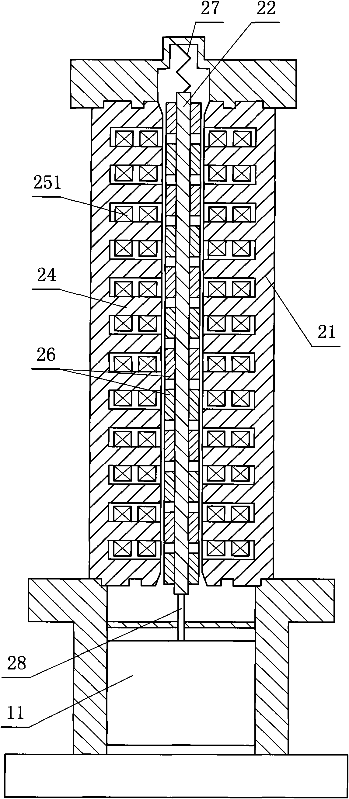
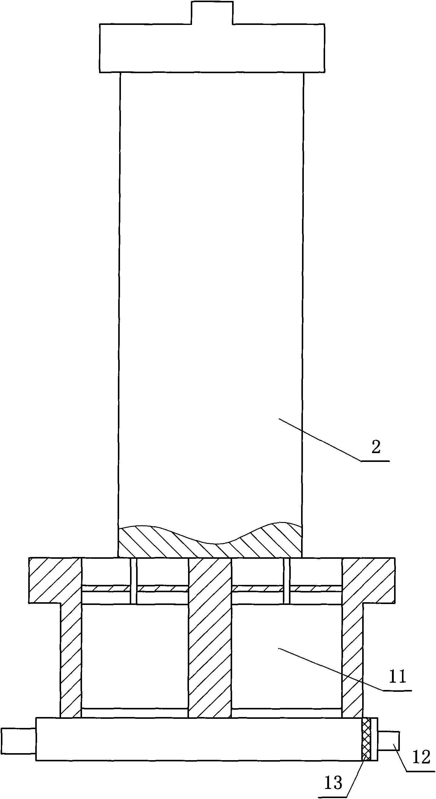
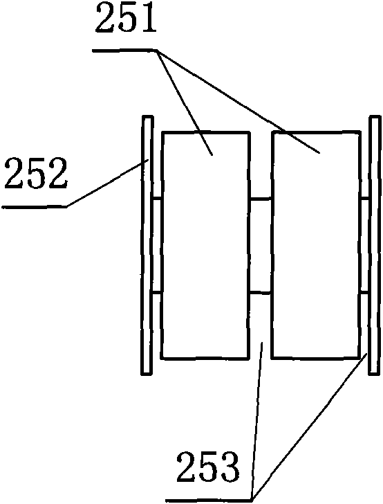
[0025] refer to figure 1 , figure 2 Embodiment 1 of an air compressor of the present invention, an air compressor includes an air pump 1, a piston 11 and an air filter 13 arranged at the air inlet 12 are arranged in the air pump 1, and a motor 2. The motor 2 includes a stator 21 and a magnetic core yoke 22. A through hole 23 is provided in the center of the stator 21, and at least one set of stator cores 24 perpendicular to the axis of the through hole 23 are arranged on the wall of the through hole 23. The stator core 24 is provided with an electromagnetic coil 251, the magnetic core yoke 22 is provided with two or more pairs of magnetic steel 26, the magnetic steel 26 N poles and S poles are arranged alternately, and the magnetic core yoke 22 is arranged in the through hole 23, one end of the magnetic core yoke 22 is provided with two connecting rods 28 connected to the piston 11 of the air pump 1, and the other end of the magnetic core yoke 22 is provided with a compressi...

Embodiment 2

[0027] refer to Figure 6 It is the second embodiment of an air compressor of the present invention. An air compressor includes two air pumps 1, the connection with one of the air pumps 1 and the internal and external structure of the motor 2 are the same as in the first embodiment, and the magnetic core yoke 22 The other end of the connecting rod 28 is also provided with at least one connecting rod 28 to be connected with the piston 11 of the second air pump 1, the compression spring 27 is sleeved on the connecting rod 28, one end of the compression spring 27 withstands the magnetic core yoke 22, and the other end of the compression spring 27 Hold the shell of the air pump 1.

[0028] When in use, connect the pipelines of the air inlet 12 and the air outlet, and energize the motor 2. After the electromagnetic coil 251 inside the motor 2 is energized, the magnetic poles generated continuously change, and the magnetic steel 26 on the magnetic core yoke 22 acts to promote The m...


PUM


Abstract

The invention discloses an air compressor, comprising at least one air pump, wherein the air pump is internally provided with a piston and an air cleaner installed at an air inlet, and further comprising an electrical motor, wherein the electrical motor comprises a stator and a magnetic core yoke, the center of the stator is provided with a through hole, the wall of the through hole is provided with at least one set of stator cores vertical to the axle of the through hole, the stator core is provided with a magnetic coil, the magnetic core yoke is provided with magnetic steel above two pairs of electrodes, the N pole and the S pole of the magnetic steel are set in alternating manner, the magnetic core yoke is installed inside the through hole, one end of the magnetic core yoke is providedwith at least one connecting bar connected with the piston of the air pump, and the magnetic core yoke is further provided with an elastic resetting device. The invention has the following advantage:the magnetic core yoke directly carries out reciprocating movement in the electrical motor to drive the piston by means of the advancement of the internal structure of the electrical motor, thereby efficiently improving the working efficiency, reducing the noises and prolonging the service life of the complete machine; and the reset position can be appointed by using the elastic resetting so as toconveniently re-start the air compressor.

Description

technical field [0001] The invention relates to an air compressor. Background technique [0002] Air is compressible, and the volume of the air is reduced by the mechanical movement of the air compressor, and the air after the pressure is increased is called compressed air. It is an important power source, and has the remarkable characteristics of no pollution, clear and transparent, convenient transportation, harmless, low flammability, and not afraid of loading. As an important form of energy generation, air compressors are widely used in machinery, metallurgy, electronic power, medicine, packaging, chemical industry, food, mining, textiles, transportation and many other industrial fields, becoming the mainstream product of compressed air. , is a device that outputs air at a standard atmospheric pressure through energy conversion to meet the needs of users. Energy conversion can generally be understood as the conversion of mechanical energy into kinetic energy. [0003] ...

Claims


Application Information

Patent Timeline
Patent Type & Authority Patents(China)
IPC IPC(8): F04B35/04H02K7/10
Inventor 姜卫亮应时立
Owner 衢州泰宏节能科技有限公司
Learn More