
Combustion device for biomass granular fuel

A biomass particle and combustion device technology, applied in the direction of solid fuel combustion, combustion equipment, lighting and heating equipment, etc., can solve the problems of low combustion efficiency, high smoke and dust, easy coking, etc., achieve high dust removal efficiency and reduce dust removal load , the effect of preventing low temperature corrosion

Inactive Publication Date: 2010-08-04
QINGDAO UNIV
View PDF0 Cites 0 Cited by
  • Summary
  • Abstract
  • Description
  • Claims
  • Application Information

AI Technical Summary

Problems solved by technology

[0004] The purpose of the present invention is to overcome the shortcomings of the prior art, seek to design and provide a combustion device with high automation, high thermal efficiency, sufficient combustion, and suitable for small and medium capacity boilers to solve the problem of fixed grate, chain furnace and reciprocating grate. Problems such as high smoke and dust, low combustion efficiency, and easy coking when burning biomass pellet fuel in the furnace layer

Method used


Image

  • Combustion device for biomass granular fuel
  • Combustion device for biomass granular fuel
  • Combustion device for biomass granular fuel

Examples


Embodiment Construction

[0011] The present invention will be further described below in conjunction with the accompanying drawings and embodiments.

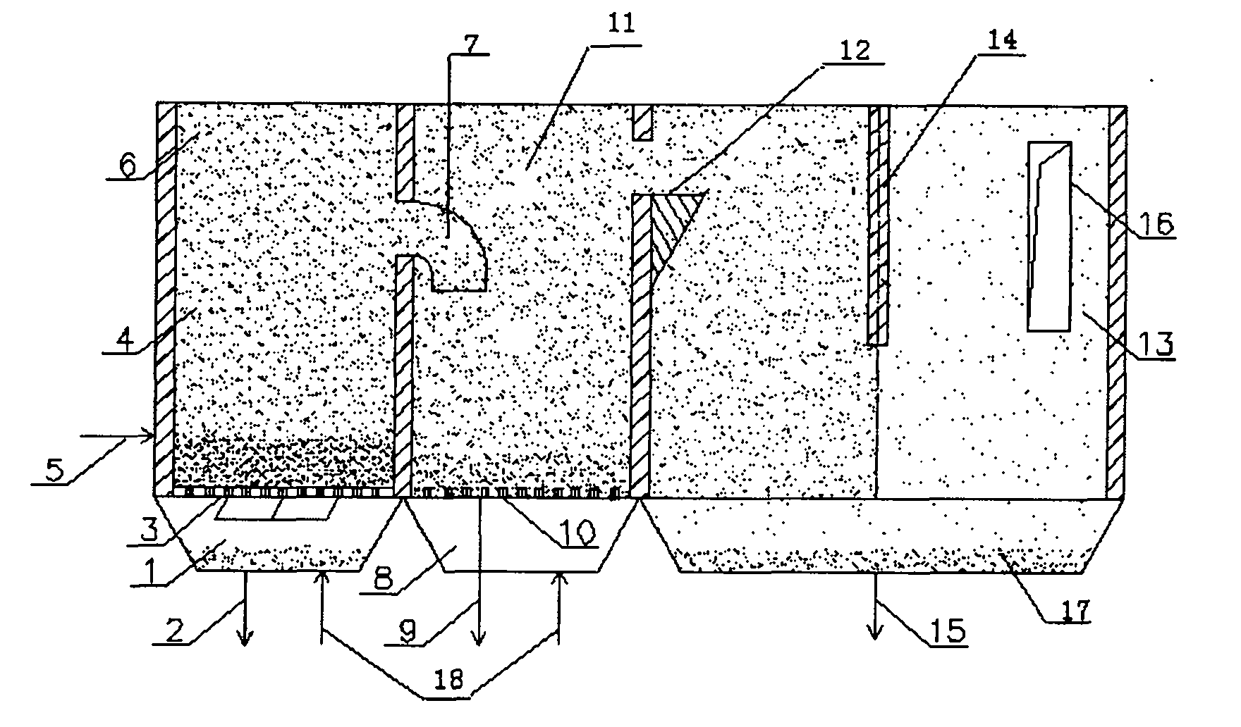
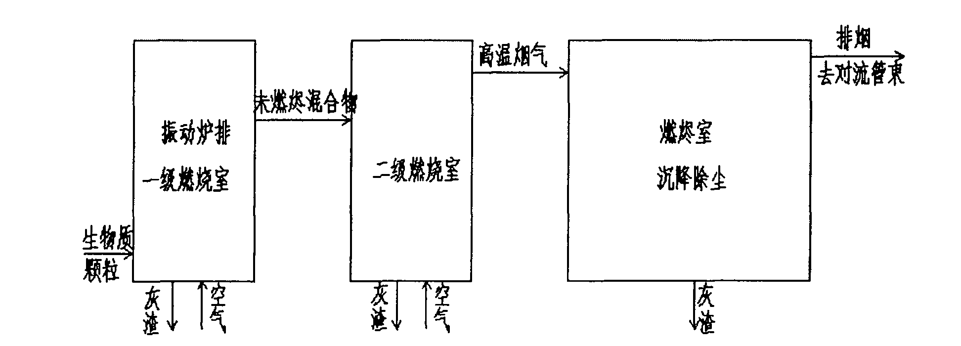
[0012] The main structure of this embodiment includes a primary air chamber 1, a regular ash outlet 2, a vibrating grate 3, a primary combustion chamber 4, a screw feeding inlet 5, a top cap cavity 6, a flue gas guide pipe 7, and a secondary air chamber 8. Periodic ash outlet pipe 9, air distribution plate 10, secondary combustion chamber 11, internal components 12, ember chamber 13, settlement dust removal retaining wall 14, regular ash removal port 15, exit chimney 16, ash accumulation chamber 17, Air supply pipe 18 and water-cooled wall pipe 19; its auxiliary equipment includes convection tube bundle, lower header, upper drum, economizer, blower fan, induced draft fan, circulating water pump, chimney, control and display platform, etc.; its primary combustion chamber 4. The secondary combustion chamber 11 and the ember chamber 13 are sequentially arr...


PUM


Abstract

The invention relates to the technical field of clean combustion energy, and relates to a device for efficiently combusting biomass granular fuel. A primary combustion chamber, a secondary combustion chamber and a burnout chamber are arranged in turn to form a communication structure and combined to form a combustion device main body; the bottom of the primary combustion chamber is manufactured with a primary air chamber with a mesa structure, the bottom end of the primary combustion chamber is provided with a periodical ash outlet and a blast pipe respectively, the lower part of the left sideof the primary combustion chamber is provided with a spiral feeding inlet, and the top space of the primary combustion chamber is provided with a top cap cavity; and the upper part of the right sideof the primary combustion chamber is provided with a downward obliquely-bent smoke guide pipe, an outlet of the smoke guide pipe extends to the middle part of the secondary combustion chamber, the topof the right side of the secondary combustion chamber is provided with an inner component in an open mode, the inner component butts the burnout chamber and the secondary combustion chamber in a communication mode, the bottom end of the secondary combustion chamber is provided with a mesa secondary air chamber and a periodical ash outlet pipe, and the bottom of the secondary air chamber is provided with a blast pipe. The combustion device has the advantages of simple structure, full combustion, high efficiency, good dust removing effect, stable and reliable running, and remarkable energy-saving effect.

Description

Technical field: [0001] The invention belongs to the technical field of clean combustion energy, and relates to a device for high-efficiency combustion of biomass particle fuel, so as to realize that the biomass particle fuel replaces coal combustion and is used in small and medium-sized boilers. Background technique: [0002] At present, urban heating has increasingly relied on the centralized heating of thermal power plant heat sources, but there are still heating "dead spots" far from the heating center, the cost of laying pipe networks is high, and the heat loss is large, which is not worth the candle; Thermal independent units such as hotels, schools, hospitals, swimming pools, etc. need flexible heating, and central heating is not suitable. Therefore, at present, there are still a lot of retail heat supply households in cities, and small self-provided heating oil and gas boilers are commonly used. The pressure faced by these heat dissipation users includes the pressure...

Claims


Application Information

Patent Timeline
Patent Type & Authority Patents(China)
IPC IPC(8): F23B10/00F23B10/02
Inventor 王翠苹王凤印
Owner QINGDAO UNIV
Learn More