Over-temperature protection device for waste gas treatment

A technology for over-temperature protection and exhaust gas treatment, which is applied in the direction of combustion methods, lighting and heating equipment, combustion types, etc., and can solve problems such as system over-temperature, shutdown, and machines

Active Publication Date: 2009-11-25
DESICCANT TECH CORP
View PDF0 Cites 3 Cited by
  • Summary
  • Abstract
  • Description
  • Claims
  • Application Information

AI Technical Summary

Problems solved by technology

[0004] However, when the concentration of the exhaust gas desorbed and discharged through the desorption zone in the enrichment wheel is too hig

Method used


Image

  • Over-temperature protection device for waste gas treatment
  • Over-temperature protection device for waste gas treatment
  • Over-temperature protection device for waste gas treatment

Examples


Embodiment Construction

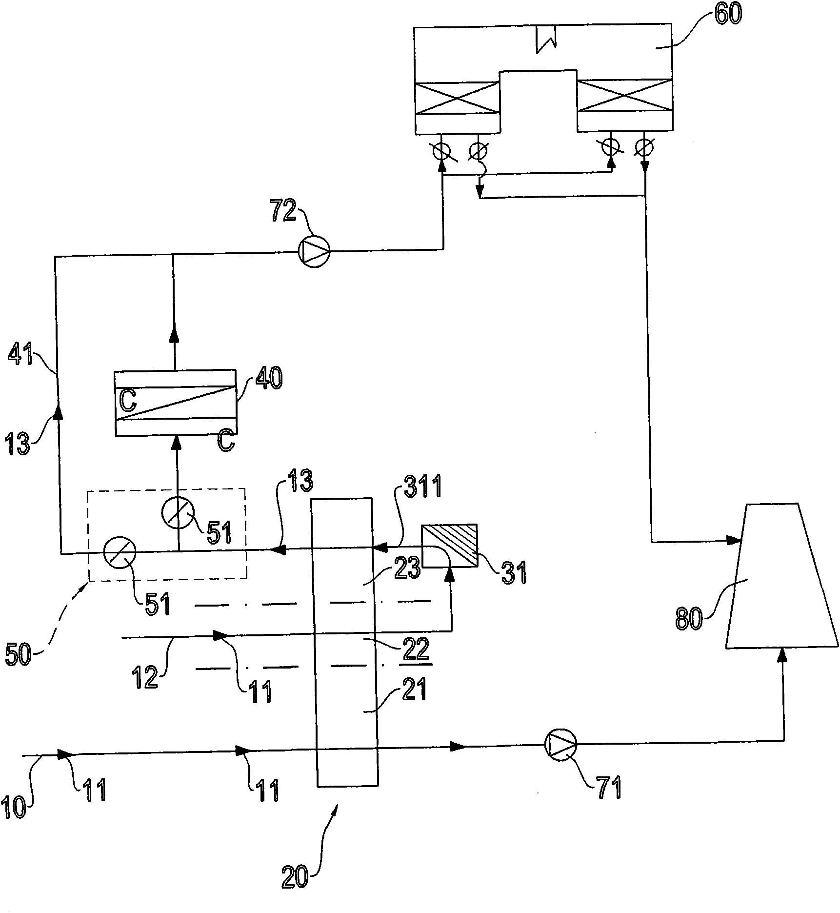
[0028] Please refer to figure 1 As shown, it is a schematic structural diagram of the exhaust gas treatment over-temperature protection device of the present invention. The exhaust gas treatment over-temperature protection device includes an exhaust gas intake pipeline 10, a concentration runner 20, a second intake pipeline 12, a heat source device 31, A heat exchanger 40 , a direction regulating valve group 50 , an exhaust bypass duct (By Pass) 41 , a combustion furnace 60 , a first exhaust fan 71 , a second exhaust fan 72 and a chimney 80 .

[0029] Wherein, the waste gas 11 of the propylene glycol monomethyl ether ester (PGMEA: Propylene Glycol MonomethylEther Acetate), propylene glycol monomethyl ether (PGME: Propylene Glycol MonomethylEther)... etc. enters from the waste gas inlet line 10, and the concentration runner 20 is divided into an adsorption zone 21, a cooling zone 22 and a desorption zone 23, and the adsorption zone 21, the cooling zone 22 and the desorption zon...


PUM


Abstract

The invention relates to an over-temperature protection device for waste gas treatment. A concentration rotating wheel of the over-temperature protection device is divided into an adsorption area, a cooling area and a desorption area, wherein a gas inlet end of a concentrated adsorption area is connected with a waste gas pipeline; a second gas inlet pipeline is connected with a gas inlet end of the cooling area and a gas inlet end of a waste gas inlet pipeline; a gas exhaust end of the cooling area is connected with a gas inlet end of a heat source device; a gas exhaust end of the heat source device is connected with a gas inlet end of the desorption are, and a gas exhaust end of the desorption area is connected with a gas inlet end of a heat exchanger; the heat exchanger is provided with a row of gas exhaust by-pass vent pipes which communicate the gas inlet end and a gas exhaust end of the heat exchanger to form a loop; a flow direction regulating valve is arranged between the gas exhaust end of the desorption and the gas inlet end of the heat exchanger to control the flow direction of waste gas; one end of a first exhaust fan is connected with the gas exhaust end of the adsorption area, while the other end of the first exhaust fan is connected with a chimney; and one end of a second exhaust fan is arranged on a pipeline formed after the heat exchanger and the gas exhaust by-pass vent pipes are connected, while the other end of the second exhaust fan is connected with a combustion furnace.

Description

technical field [0001] The invention relates to an over-temperature protection device for waste gas treatment, especially a waste gas intake pipeline, a concentration runner, a second intake pipeline, a heat source device, a heat exchanger, a direction regulating valve group, The combined design of an exhaust bypass duct (By Pass), a combustion furnace, a first exhaust fan, a second exhaust fan and a chimney makes the present invention have the ability to control the exhaust gas concentration to avoid system damage due to excessive exhaust gas concentration. The effect of shutdown and machine damage is suitable for the application of exhaust gas treatment systems, such as factories...etc. Background technique [0002] With the vigorous development of high-tech industries, the semiconductor industry such as integrated circuit industry and optoelectronic industry has also grown rapidly. Environmental protection issues, for example: semiconductor factories will use various cle...

Claims


Application Information

Patent Timeline
IPC IPC(8): F23G7/06
Inventor 郑石治扶亚民田磊徐瑞珠刘邦昱洪守铭
Owner DESICCANT TECH CORP
Why Eureka
Try Eureka