
Method for automatic fault diagnosis of satellite and diagnostic system thereof

A fault diagnosis system and fault diagnosis technology, which are applied in the fields of space navigation equipment, space navigation aircraft, and space space vehicle observation, etc., can solve the problems of large time delay, high false alarm, and inaccurate division of periodic fault signals. , to achieve the effect of reducing the false alarm rate and the false alarm rate

Inactive Publication Date: 2009-12-02
SHANGHAI ENG CENT FOR MICROSATELLITES
View PDF0 Cites 58 Cited by
  • Summary
  • Abstract
  • Description
  • Claims
  • Application Information

AI Technical Summary

Problems solved by technology

Due to the harsh environment in which the satellite operates, affected by various interference noises, some signals may appear to be inconsistent with the theoretical value instantaneously, which will lead to excessive false alarms
[0005] Michael A.Swartwoout and others proposed the Persistence-Counter method for the shortcomings of production rules and applied it to satellites such as Sapphire and Emerald, which can significantly reduce the false alarm rate. However, the fault detection capability still has shortcomings, for example, the detection of periodic fault signals has the disadvantage of large time delay
There are two main reasons for the above shortcomings: (1) In the actual detection, due to the influence of the environment, conditions, detection content and technical means, there is a certain uncertainty in the detection value itself. Uncertainty in division due to the intermediate transition of differences between things, which is the inherent imprecision of things themselves
However, the fault detection method based on limit-checking divides inaccurate detection values ​​through precise threshold values, which will inevitably lead to false alarms and false negatives; The Influence of Environmental Uncertainty Factors

Method used


Image

  • Method for automatic fault diagnosis of satellite and diagnostic system thereof
  • Method for automatic fault diagnosis of satellite and diagnostic system thereof
  • Method for automatic fault diagnosis of satellite and diagnostic system thereof

Examples


Embodiment Construction

[0050] In order to make the technical means, creative features, goals and effects achieved by the present invention easy to understand, the present invention will be further described below in conjunction with specific illustrations.

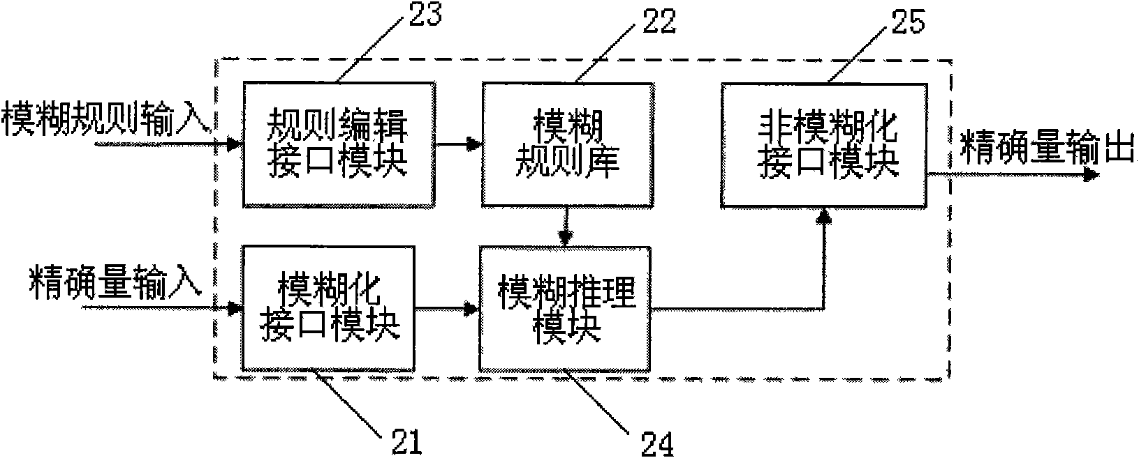
[0051] Such as figure 1 Shown, the autonomous satellite fault diagnosis system of the present invention, it comprises: data input device 10, fault detection device 20, fault inference device 30 and fault countermeasure output device 40; Data input device 10 is used for receiving the real-time telemetry data of satellite, and Perform data preprocessing tasks such as filtering, eliminating error frames, and telemetry data conversion, and then input the fault detection device 20; the fault detection device 20 performs fault detection based on fuzzy sets on the real-time telemetry data of the satellite, and starts the fault inference device based on the fault detection result 30 performs inference; the fault reasoning device 30 performs fault reason...


PUM


Abstract

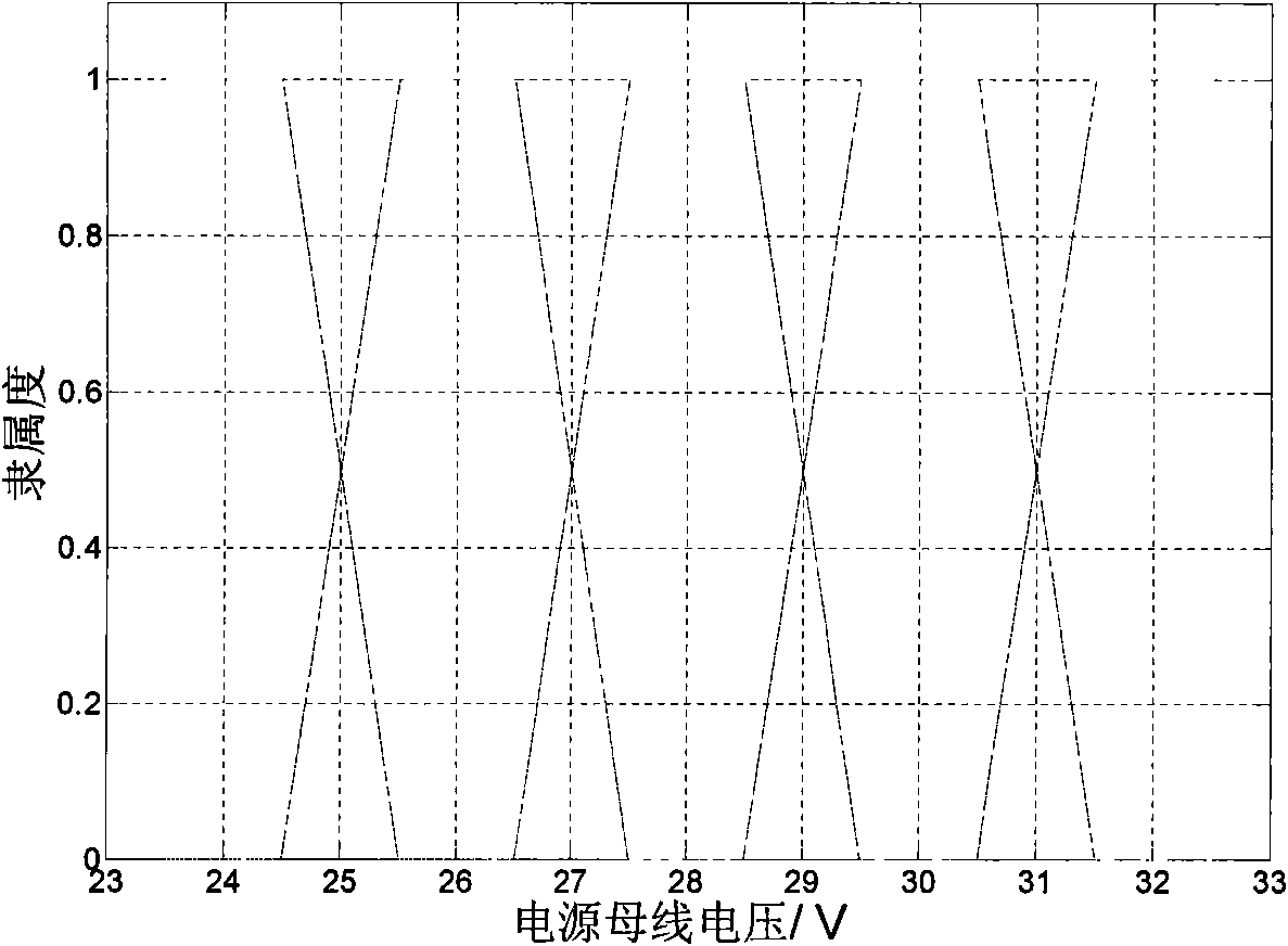
The invention relates to a method for automatic fault diagnosis of a satellite and a diagnostic system thereof. The method comprises the following steps: dividing the satellite fault into a component level fault, a subsystem level fault and a system level fault; adopting a fault detection method based on a fuzzy set to fuzzify a precise sensor sampling value; defining different alarm weight values for fuzzy subset based on the membership grade belonging to each fuzzy subset; and determining whether to alarm or not by calculating the relation between the summation of the alarm weight values in a time window and an alarm threshold value. The method can effectively overcome the defects of a common fault detection method and effectively reduce the false alarm rate and the rate of missing report; and when certain fault is caused by a plurality of sub-faults, the method performs heuristic search according to the reliability of a system corresponding to each sub-fault and searches a sub-fault node corresponding to a system with low reliability preferentially. Besides, in order to adapt to the synergistic diagnosis between distributed satellites in the future, a synergistic interface is designed to provide diagnosis services for other satellites, thus the aim of the invention is achieved.

Description

technical field [0001] The invention relates to a spacecraft fault diagnosis method and a diagnostic system thereof, in particular to a satellite autonomous fault diagnosis method and a diagnostic system for autonomously performing fault diagnosis according to real-time telemetry parameter messages. Background technique [0002] The development trend of autonomous intelligent control of satellites and autonomous operation of distributed satellites requires the spacecraft to have the functions of autonomously sensing its own health status and autonomous fault diagnosis. However, at the present stage, my country's spacecraft faults mainly rely on the ground measurement and control station for diagnosis, which limits the fault diagnosis of satellites to the location of the ground measurement and control station and the measurement and control arc, and also brings great difficulties to the measurement and control personnel of the ground measurement and control station. Judge stre...

Claims


Application Information

Patent Timeline
IPC IPC(8): B64G1/66B64G3/00
Inventor 姜连祥李华旺常亮
Owner SHANGHAI ENG CENT FOR MICROSATELLITES
Learn More