
Electromagnetic folding brake for tractor

A technology of traction machines and brakes, which is applied in the direction of hoisting devices, etc., can solve the problems of unsatisfactory spring safety factor, increased cost, and difficult processing, etc., to meet the needs of market competition, low manufacturing and installation costs, and simple processing technology Effect

Active Publication Date: 2009-12-02
浙江西子富沃德电机有限公司 +1
View PDF1 Cites 23 Cited by
  • Summary
  • Abstract
  • Description
  • Claims
  • Application Information

AI Technical Summary

Problems solved by technology

[0004] Although the above-mentioned patented technical solution has its advantages, it has the following technical problems: First, its magnetic circuit is already saturated, so it is difficult to increase the braking force
Because the spring safety factor cannot meet the spring design requirements, if the spring force is increased, the external volume of the brake must increase, resulting in an increase in cost, which cannot match the original factory
Secondly, the static plate is a machined solid part with an elliptical groove. Due to the narrow width and deep depth of the groove, processing is difficult and time-consuming, and the cost is also high.
Finally, because the hollow screw not only acts as a link but also as an adjustment, if the braking force is to be increased, the safety factor of the hollow screw cannot be satisfied. It is very small, and the safety factor is also small, and after the braking force of the brake is adjusted before leaving the factory, it cannot be adjusted again

Method used


Image

  • Electromagnetic folding brake for tractor
  • Electromagnetic folding brake for tractor
  • Electromagnetic folding brake for tractor

Examples


Embodiment Construction

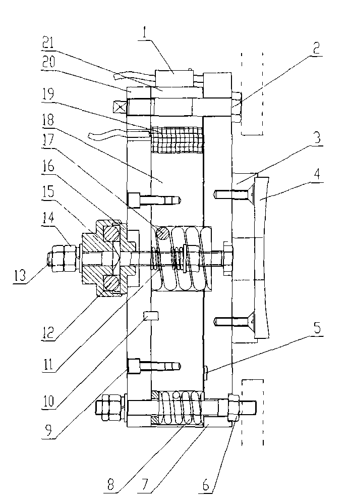
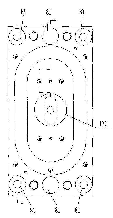
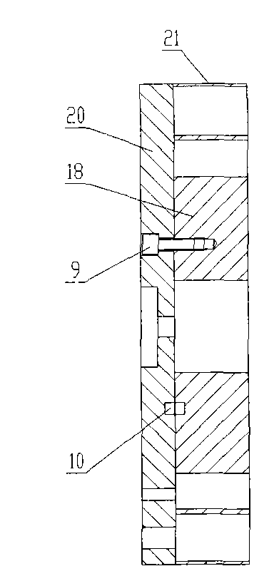
[0019] The present invention will be described in detail below in conjunction with the accompanying drawings.

[0020] Such as Figure 1-3 As shown, the electromagnetic stack brake for the traction machine includes a magnetic top plate 7, an iron core assembly, an adjustment bolt 2, a stud bolt 6, a brake spring 8, a brake spring 17, an electromagnetic coil 19, a brake pad 4, a micro-movement A switch 1 and a manual brake release device, wherein: the iron core assembly includes an iron core bottom plate 20 , an iron core inner ring 18 , and an iron core outer ring 21 . An electromagnetic stack brake is installed on the upper part of the left and right sides of the elevator traction machine. When one of the brakes fails, the other can still brake the main engine of the elevator to ensure the safe operation of the elevator.

[0021] The magnetic top plate 7 and the iron core bottom plate 20 are arranged in parallel, and there is a space between the inner surfaces of the two. Th...


PUM


Abstract

The invention relates to an electromagnetic folding brake for a tractor. A magnetic top plate and an iron core base plate are arranged in parallel, and a space is reserved between the magnetic top plate and the iron core base plate; the magnetic top plate and the iron core base plate are connected by an adjusting bolt; the magnetic top plate can move along the adjusting bolt, and the outer lateral surface of the magnetic top plate is fixedly provided with a braking plate; an inner ring of the iron core and an outer ring of the iron core are fixed on the inner lateral surface of the iron core base plate; gaps are reserved between the inner ring of the iron core and the outer ring of the iron core and the inner lateral surface of the magnetic top plate; an electromagnetic coil is embedded between the inner ring of the iron core and the outer ring of the iron core, and the electromagnetic coil leads out a coil wire; a plurality of stud bolts penetrate the magnetic top plate, the iron core base plate and the outer ring of the iron core, braking springs are sleeved on the outside of the stud bolts, and both ends of the braking springs are pressed against the magnetic top plate and the inner lateral surface of the iron core base plate respectively; and a micro switch is arranged on the outer side of the outer ring of the iron core, and when the magnetic top plate acts, a protruding part of the magnetic top plate contacts the micro switch to make the micro switch act. The brake has the advantages of simple structure, low cost, easy adjustment of the gaps, good braking performance, little noise, low wear and the like.

Description

technical field [0001] The invention belongs to the technical field of elevator safety device manufacture, in particular to an electromagnetic stack brake for a traction machine. Background technique [0002] The brake is an important safety component of the elevator traction machine. On the premise of ensuring and improving the braking performance and quality, its manufacturing cost should be reduced as much as possible. [0003] The existing electromagnetic double-push brake has disadvantages such as complex structure, high manufacturing and installation costs, high noise, and serious wear of the lever, which greatly affects the comfort of the elevator. For this reason, Chinese Patent No. ZL200520015258.5 discloses an electromagnetic stack brake for a traction machine, which consists of a static plate, a moving plate, an electromagnetic coil, a micro switch, a brake spring, a brake pad and a manual release device; The static plate and the moving plate are relatively combi...

Claims


Application Information

Patent Timeline
IPC IPC(8): B66D5/14B66D5/30
Inventor 杨志华邹家春梅金丽马新峰黄锡军郎小东
Owner 浙江西子富沃德电机有限公司
Learn More