Method for determining initial position angle of rotor of permanent magnet synchronous motor

A permanent magnet synchronous motor, rotor initial position technology, applied in the control of generators, electronic commutators, motor generator control and other directions, can solve the problems of easy detection failure, complex logic judgment, etc., to improve reliability and clear logic , the effect of enhancing noise immunity

Active Publication Date: 2009-12-02
HARBIN INST OF TECH
View PDF2 Cites 49 Cited by
  • Summary
  • Abstract
  • Description
  • Claims
  • Application Information

AI Technical Summary

Problems solved by technology

[0009] The purpose of the present invention is to solve the problem that the detection method of the initial position of the motor rotor in the AC servo system and the rotor detection method

Method used


Image

  • Method for determining initial position angle of rotor of permanent magnet synchronous motor
  • Method for determining initial position angle of rotor of permanent magnet synchronous motor
  • Method for determining initial position angle of rotor of permanent magnet synchronous motor

Examples


specific Embodiment approach 1

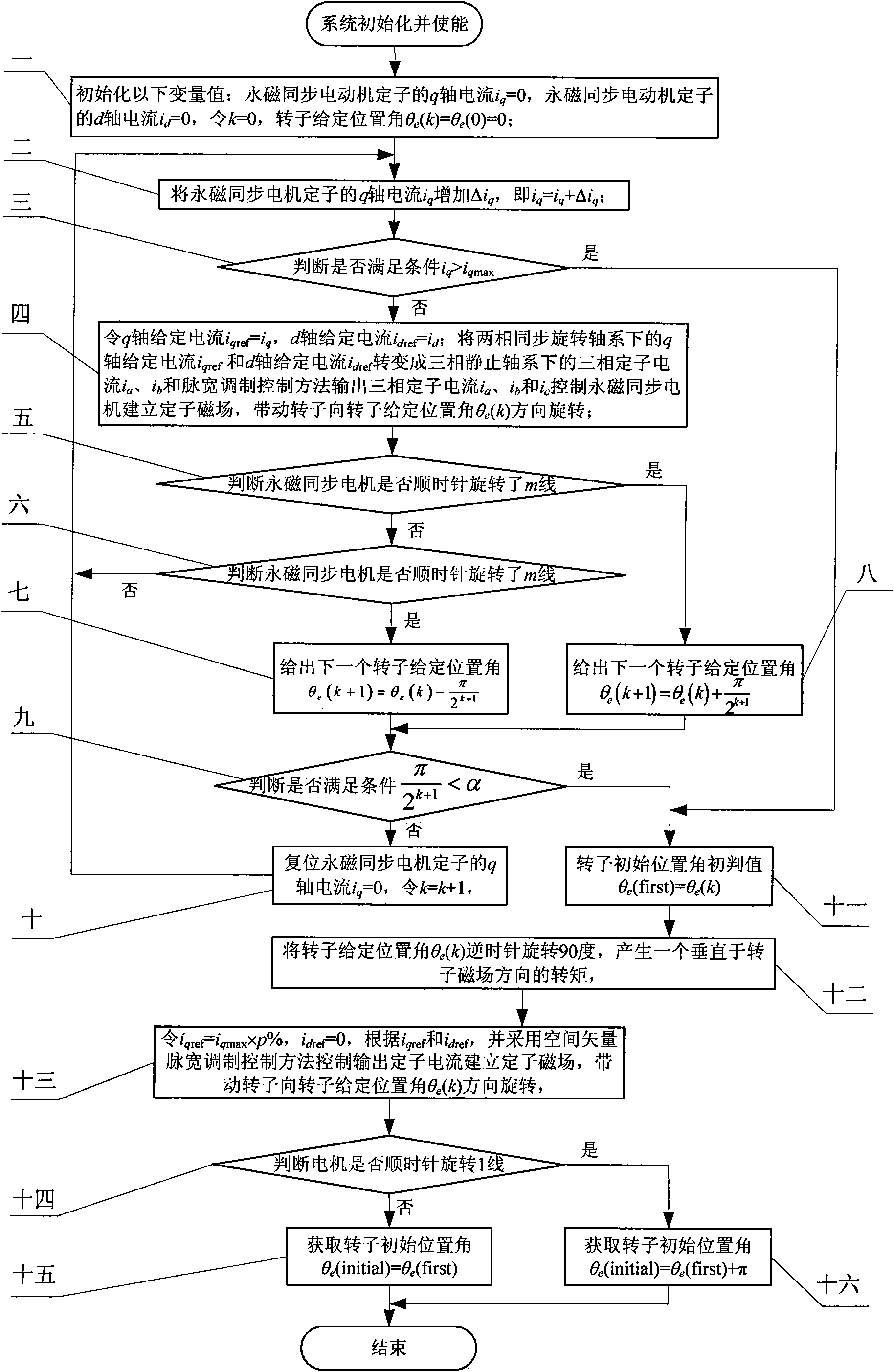
[0038] Specific implementation mode one: the following combination Figure 1 to Figure 4 Describe this embodiment, the method of this embodiment includes the following steps:

[0039] Step 1. Initialize the following variable values:

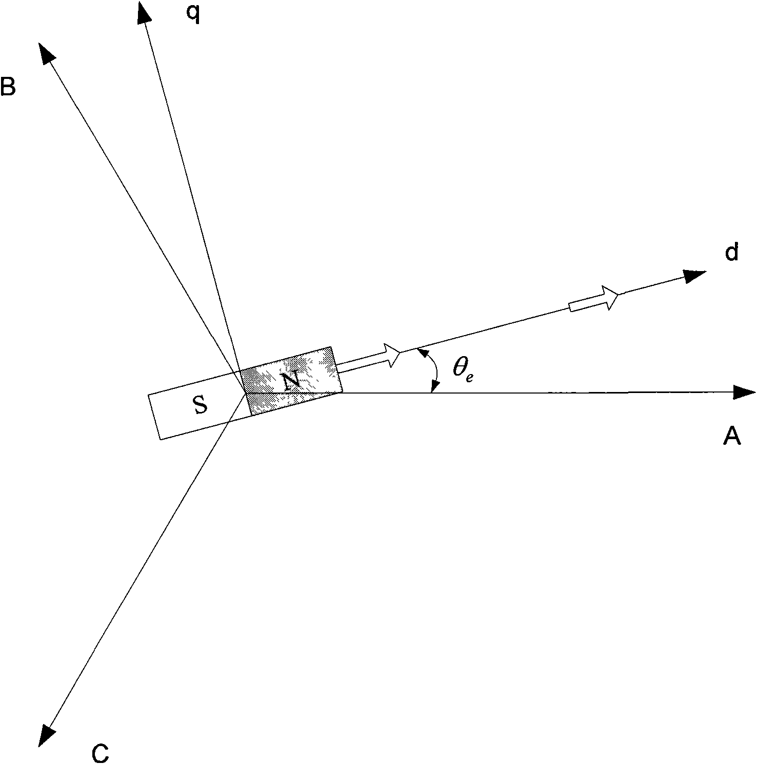
[0040] The q-axis current i of the permanent magnet synchronous motor stator q = 0, the d-axis current i of the permanent magnet synchronous motor stator d =0, let k=0, the rotor given position angle θ e (k) = θ e (0)=0,

[0041] Step 2: The q-axis current i of the permanent magnet synchronous motor stator q Increase Δi q , namely i q = i q +Δi q , Δi q is the incremental value of the q-axis current, Δi q Take the q-axis current limit value i of the permanent magnet synchronous motor stator q max 1% to 5% of

[0042] Step 3: Determine whether condition i is met q ≥i q max ,

[0043] If the judgment result is yes, go to step 11, if the judgment result is no, go to step 4,

[0044] Step 4: Let the q-axis set the current i qref = ...

specific Embodiment approach 2

[0092] Specific implementation mode two, the following combination figure 1 , image 3 and Figure 4 Describe this embodiment. The difference between this embodiment and Embodiment 1 is that the method for judging whether the motor has rotated m lines clockwise in step 5 is:

[0093] An incremental encoder is used to measure the position information of the rotor of the permanent magnet synchronous motor. When the incremental encoder outputs m pulses and the output A pulse lags the B pulse by 90 degrees, the permanent magnet synchronous motor rotates clockwise Line m.

[0094] In step 6, the method of judging whether the motor has rotated the m line counterclockwise is as follows:

[0095] An incremental encoder is used to measure the position information of the permanent magnet synchronous motor rotor. When the incremental encoder outputs m pulses and the output A pulse is 90 degrees ahead of the B pulse, the permanent magnet synchronous motor rotates counterclockwise Line...

Embodiment approach 1

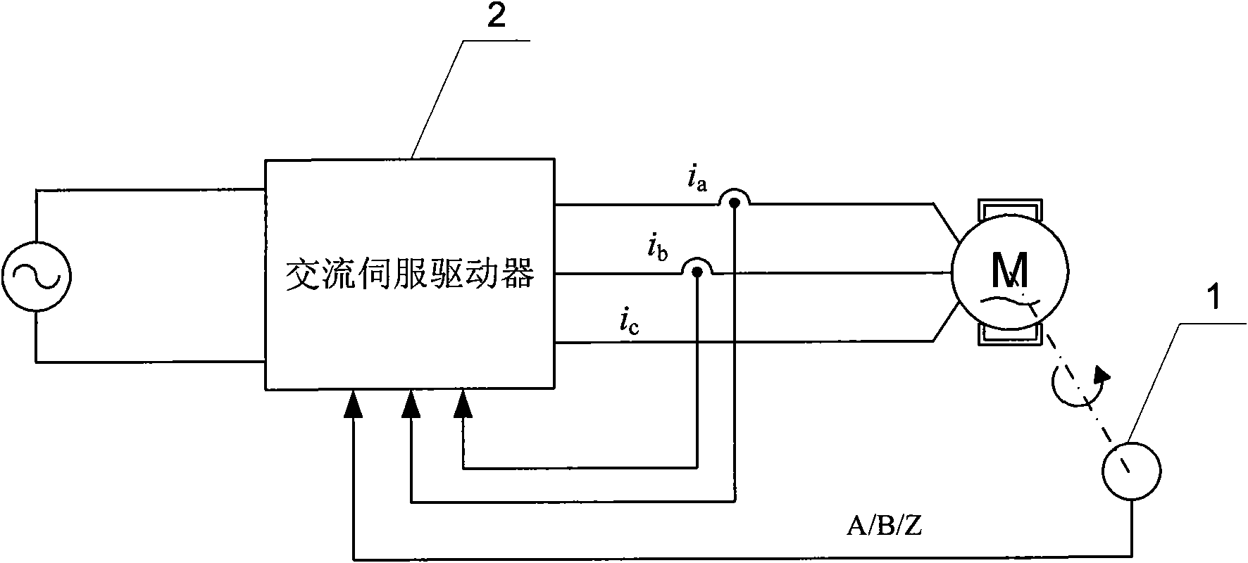
[0098] The method for determining the rotor initial position angle of the permanent magnet synchronous motor described in Embodiment 1 is compiled into a rotor initial position detection program, which is set in a digital signal processor (DSP), and the AC servo drive 2 uses the digital signal processor (DSP) as the The core is to use the incremental encoder 1 to measure the position information of the rotor of the permanent magnet synchronous motor, that is, the A / B / Z signal, and the A / B / Z signal is output to the digital signal processor after being processed by the conditioning circuit.

[0099]The characteristic of incremental encoder 1 is that it only outputs three pulse signals of A, B, and Z, wherein the A and B signals are orthogonal. When the permanent magnet synchronous motor rotates forward, the phase of the A pulse is 90 degrees ahead of the B pulse. When the permanent magnet synchronous motor reverses, the A pulse phase lags behind the B pulse by 90 degrees, and the...


PUM


Abstract

The invention relates to a method for determining an initial position angle of a rotor of a permanent magnet synchronous motor, which belongs to the field of motor control. The invention aims to solve the problems that a rotor detection method provided by a patent of a method and a device for detecting an initial position of a motor rotor in an alternating current servo system has complex logical decision and easy failure of detection. The method for determining the initial position angle of the rotor of the permanent magnet synchronous motor comprises the following steps: controlling the amplitude and the phase of the current of a d shaft and a q shaft under a two-phase synchronous rotating shaft system to further control the amplitude and the phase of the current of a three-phase stator under a three-phase stationary shaft system; controlling the rotation of the motor rotor under a given stator magnetic field; and according to a pulse signal fed back by an incremental encoder, making the direction of the given magnetic field gradually and circularly approach the actual position angle of the rotor until the direction of the given stator magnetic field corresponding to the current of the d shaft and the q shaft is coincident with the direction of a rotor magnetic field. The direction of a given stator current magnetic field is changed by 90 degrees, so that a torque vertical to the direction of the rotor magnetic field is generated on the rotor, and according to the rotating direction of the rotor, the initial position angle of the actual rotor is determined.

Description

technical field [0001] The invention relates to a method for determining the initial position angle of a rotor of a permanent magnet synchronous motor, belonging to the field of motor control. Background technique [0002] Accurate position and speed feedback information is required in the AC servo system. Its position detection unit is used as a feedback device, which is the guarantee of system accuracy. On the one hand, it provides the position information necessary for coordinate transformation for the system vector control; it provides position feedback for the position loop in the position servo system. On the other hand, due to mechanical installation and cost issues, the servo system is generally no longer equipped with a speed sensor, but the rotational speed value is estimated from the position information. Therefore, the rotor position information plays a very important role in the servo system. [0003] In permanent magnet synchronous motors, position sensors g...

Claims


Application Information

Patent Timeline
IPC IPC(8): H02P21/00H02P6/16H02P21/18
Inventor 杨明王宏佳徐殿国牛里
Owner HARBIN INST OF TECH
Why Eureka
Try Eureka