Heat radiating device and manufacturing method thereof

A technology of heat dissipation device and manufacturing method, which is applied in the direction of cooling/ventilation/heating transformation, indirect heat exchanger, heat exchange equipment, etc., which can solve the problems of limiting the heat transfer performance of metals and affecting the heat dissipation performance of heat dissipation devices, so as to increase contact The effect of area and high heat dissipation performance

Inactive Publication Date: 2009-12-02
FU ZHUN PRECISION IND SHENZHEN +1
View PDF0 Cites 6 Cited by
  • Summary
  • Abstract
  • Description
  • Claims
  • Application Information

AI Technical Summary

Problems solved by technology

As the size of the central processing unit becomes smaller and smaller, its heat generation becomes more concentrated. Due to the heat transfer performance of the metal, the heat at the center of the base cannot quickly spread to the entire heat sink, which affects the heat dissipation performance of the heat sink.

Method used


Image

  • Heat radiating device and manufacturing method thereof
  • Heat radiating device and manufacturing method thereof
  • Heat radiating device and manufacturing method thereof

Examples


Embodiment Construction

[0012] The heat sink of the present invention will be further described below with reference to the drawings.

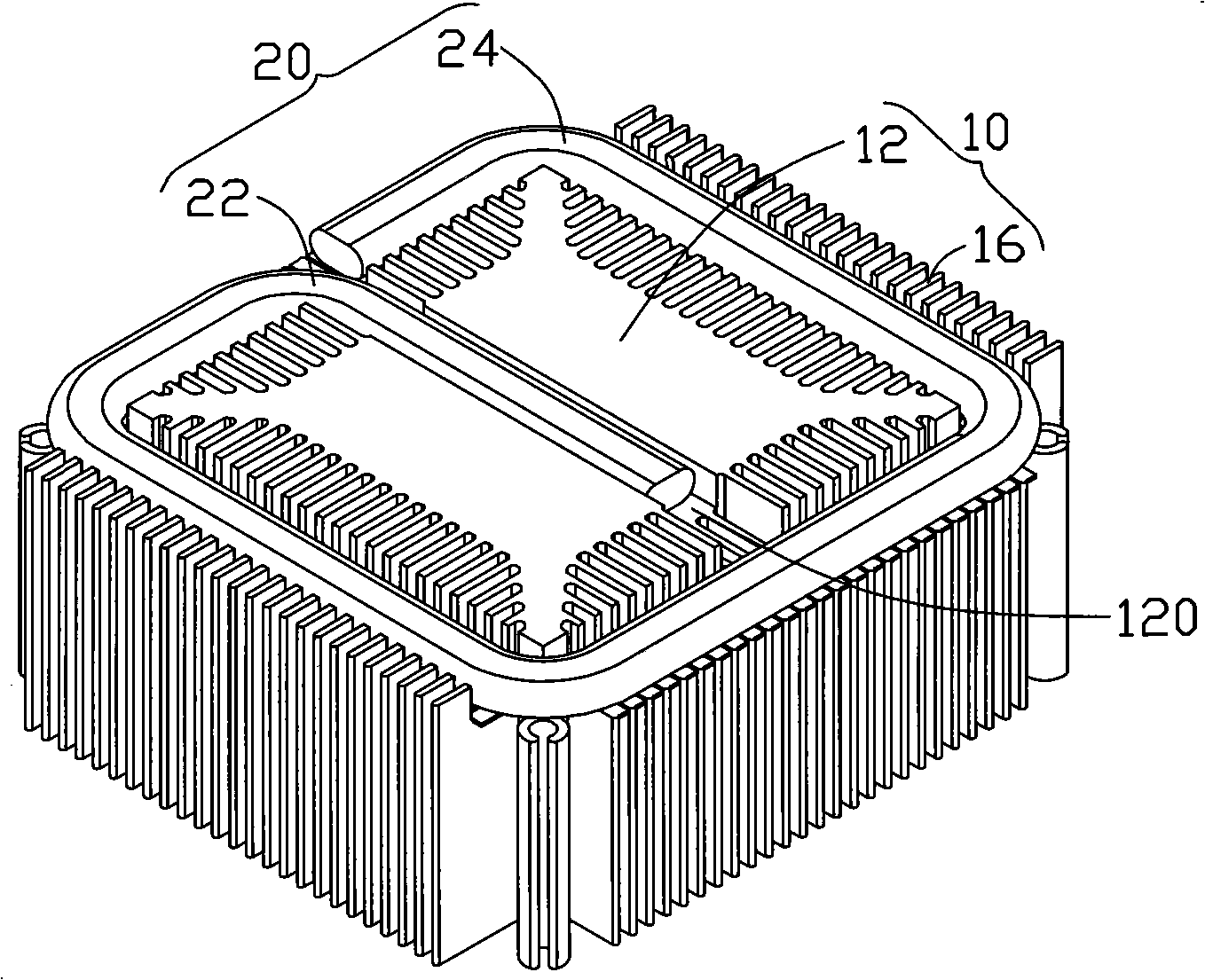
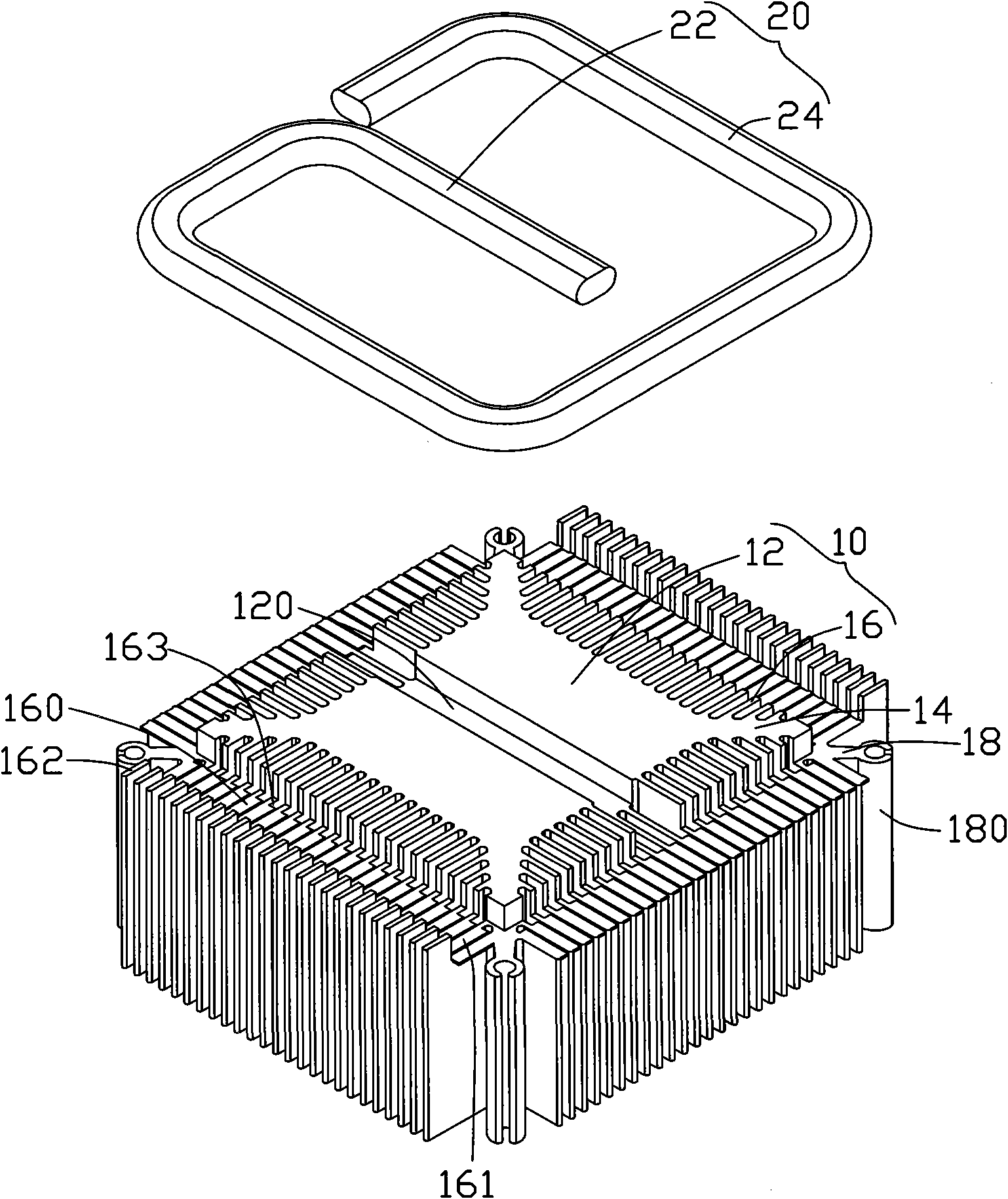
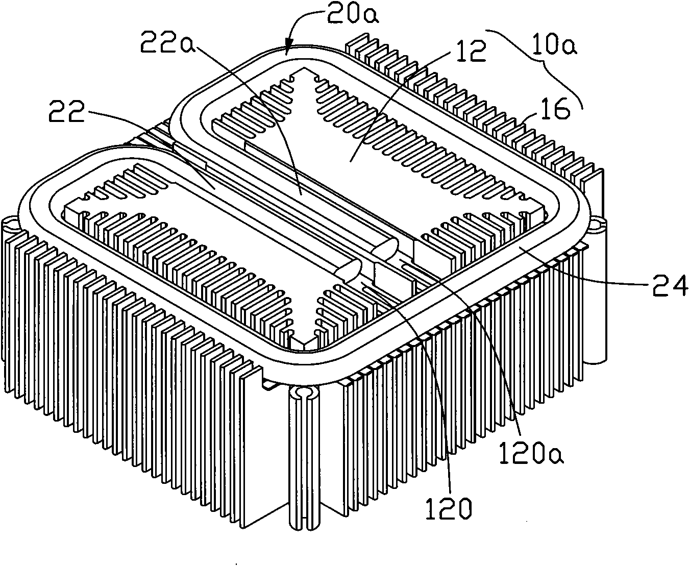
[0013] figure 1 and figure 2 Shown is the first embodiment of the heat sink of the present invention. The heat dissipation device includes an aluminum extruded radiator 10 and a heat pipe 20.

[0014] The heat sink 10 includes a main body such as a column 12 and a plurality of heat sinks 16 extending radially from the periphery of the column 12. The top surface of the column 12 forms a plane that contacts and absorbs the surface of the heating electronic component. The heat sink 16 is used to conduct and radiate the heat on the column 12. In this embodiment, the column 12 is a quadrangular prism. The four corners of the column 12 are provided with a heat-conducting branch 14 radiating outward, and part of the heat sink 16 extends from the heat-conducting branch 14. Each thermally conductive branch portion 14 of the column 12 respectively extends a locking plate 18 nea...


PUM


Abstract

The invention relates to a heat radiating device which comprises a heat radiator and a heat pipe, wherein the heat radiator comprises a body and a plurality of heat radiating fins which are formed by radially extending from the body; the top surface of the heat radiator is provided with a groove and a bearing surface; the bearing surface is arranged around the groove and is communicated with the groove; and the heat pipe is extended and arranged on the groove and the bearing surface. Because the groove and the bearing surface are formed on the heat radiating device and the heat pipe is arranged in the heat radiating device, heat can be quickly and evenly distributed to the whole heat radiating device and radiated.

Description

Technical field [0001] The invention relates to a heat dissipation device, in particular to a heat dissipation device for electronic components and a method for manufacturing the heat dissipation device. Background technique [0002] With the continuous development of the electronic information industry, the operating frequency and speed of electronic components (especially the central processing unit) are constantly increasing. However, high-frequency and high-speed will increase the heat generated by electronic components, causing their temperature to continue to rise, which seriously threatens the performance of electronic components during operation. To ensure the normal operation of electronic components, a large amount of electronic components must be discharged in time Heat. [0003] For this reason, a heat sink commonly used in the industry generally includes a base and a plurality of heat sinks arranged on the base. The base has a smooth bottom surface for being attached...

Claims


Application Information

Patent Timeline
Patent Type & Authority Applications(China)
IPC IPC(8): H05K7/20H01L23/34H01L23/367H01L23/427B23P15/26
CPCH01L23/427H01L23/467F28F1/12F28D15/0266H01L2924/0002Y10T29/49353Y10T29/4935H01L2924/00
Inventor 杨明钟徐俊朱寿礼郭青磊
Owner FU ZHUN PRECISION IND SHENZHEN
Why Eureka
Try Eureka