Numerically-controlled precise grinding polisher

A polishing machine, a precise technology, applied in grinding/polishing equipment, machine tools suitable for grinding workpiece planes, grinding machines, etc. , lack of precise control of speed, etc., to achieve the effect of stable speed regulation, wide speed change range and fast response speed

Inactive Publication Date: 2009-12-09
LANZHOU RAPID INDGRPCO
View PDF1 Cites 23 Cited by
  • Summary
  • Abstract
  • Description
  • Claims
  • Application Information

AI Technical Summary

Problems solved by technology

[0002] The traditional grinding and polishing machine is often driven by an ordinary motor, and the transmission of the upper and lower polishing discs and the inner and outer ring gears is realized through the gear transmission system, so as to realize the grinding and polishing of the workpiece. There are only two speed ratios between the upper and lower polishing discs and the planetary gear, which limits the The change of the machining trajectory of the double-sided polishing machine lacks precise control of the speed
[0003] The Chinese invention patent with the application number of 200710068275.9 discloses a control system for a precision double-sided polishing machine. The precision double-sided polishing machine adopts the principle of four frequency conversion motors to drive the upper and lower polishing discs and the inner and outer ring gears respectively to realize the transmission. The shaft sleeve structure is adopted, although the stepless speed regulation, soft start and soft stop of the processing process are realized, and the working efficiency and processing accuracy of the polishing machine are improved, but because the frequency conversion motor needs to be controlled by a frequency converter, it has higher requirements on the use conditions , slow dynamic response, poor anti-interference ability, and not suitable for high-torque processing requirements; especially for high-precision grinding and polishing equipment, the manufacturing error of the shaft sleeve structure itself will also cause the upper and lower grinding discs to jump and vibrate, thus Can not meet the processing requirements of high precision and ultra-high precision

Method used


Image

  • Numerically-controlled precise grinding polisher
  • Numerically-controlled precise grinding polisher
  • Numerically-controlled precise grinding polisher

Examples


Embodiment Construction

[0018] Below in conjunction with the preferred embodiment shown in accompanying drawing, be described in further detail:

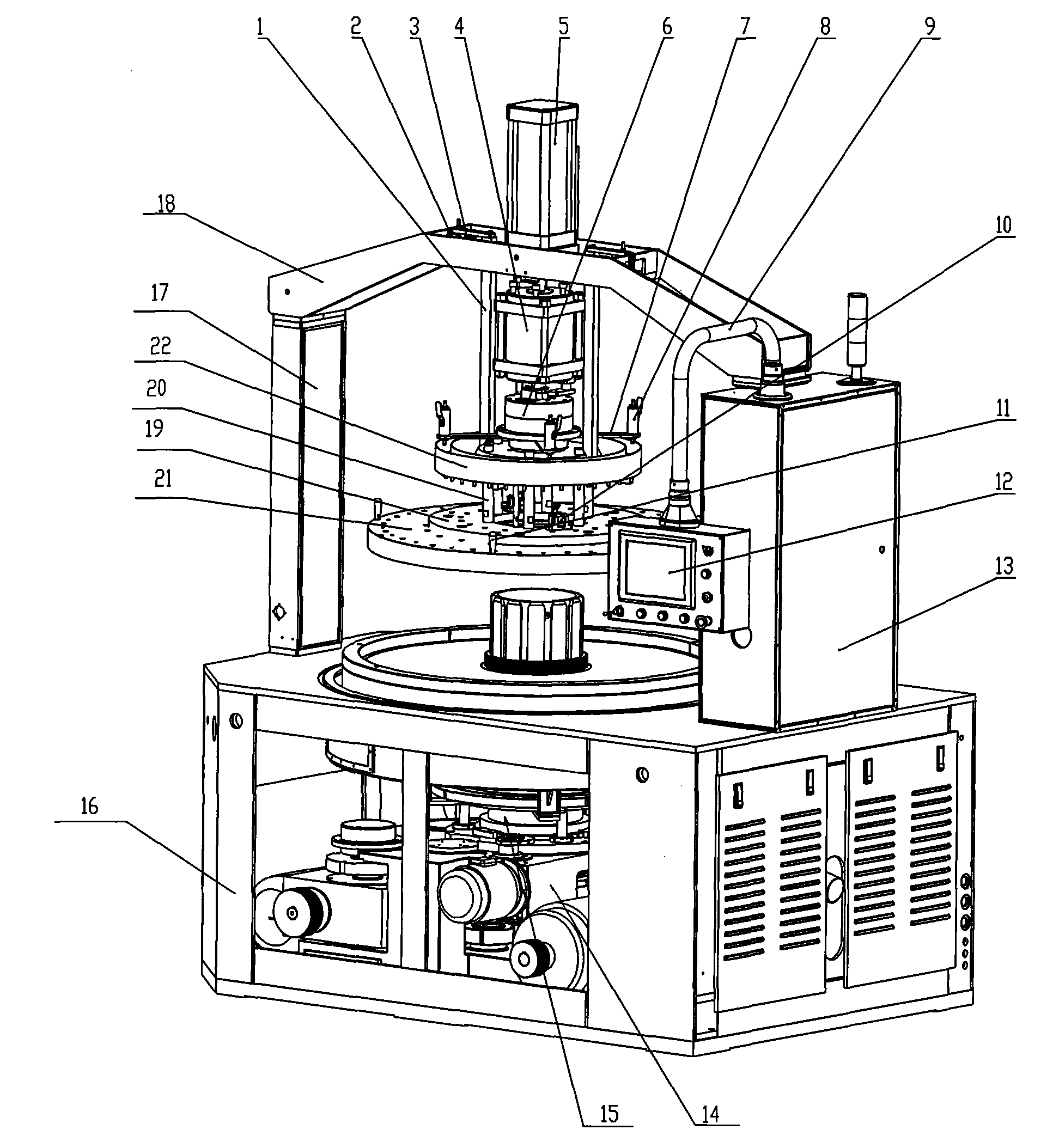
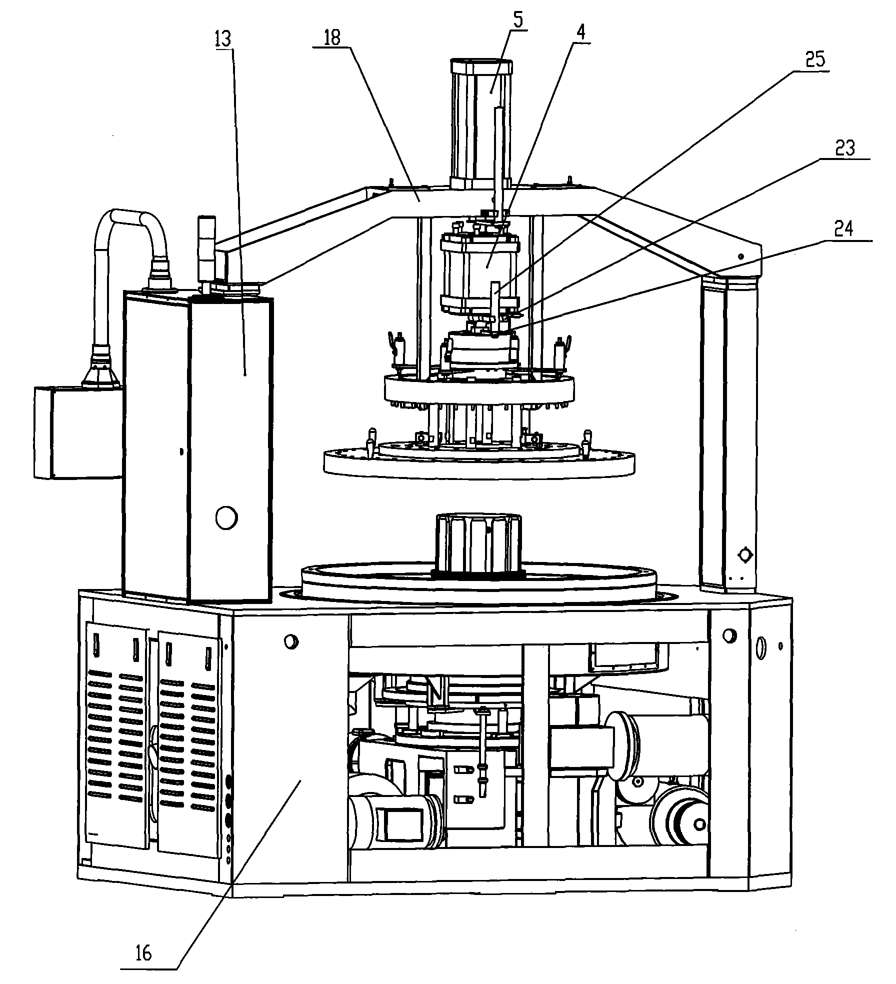
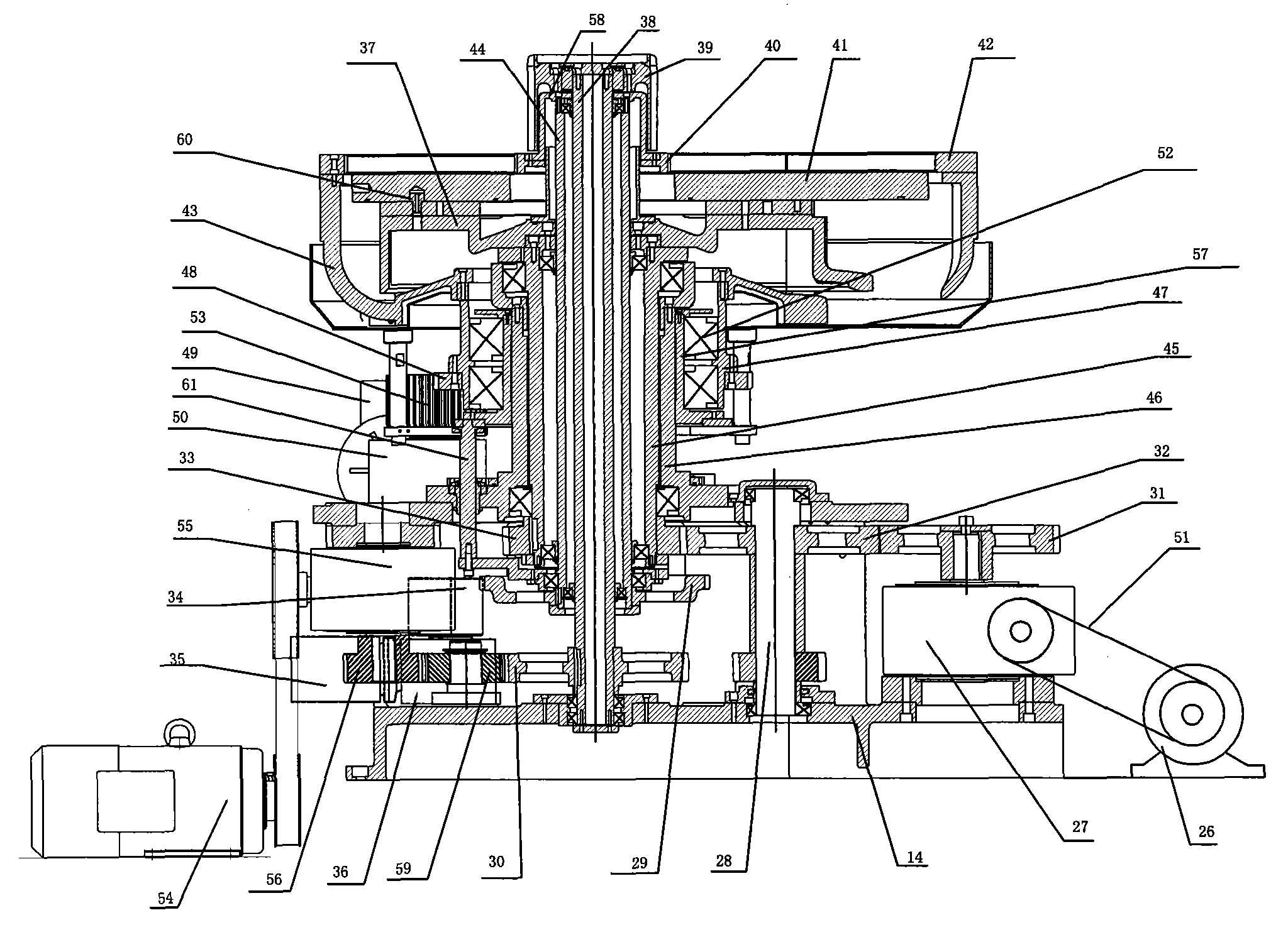
[0019] See figure 1 , 2 3. The numerically controlled precision grinding and polishing machine includes a welding box 16, one side of the welding box 16 is provided with a column 17, the other side of the welding box 16 is provided with an electrical cabinet 13, and the two ends of the beam 18 Fixedly installed on the column 17 and the electrical cabinet 13 respectively, the main support 14 in the welding box 16 is provided with a main shaft drive system 15, and the position corresponding to the main shaft drive system 15 is provided with an upper plate device on the beam 18, and the operation box 12 The supporting arm 9 of the operation box is arranged on the electrical cabinet 13, and it is characterized in that it also includes: the cylinder rod of the fast acting cylinder 5 of the upper plate device is fixedly installed in the center of the crossbeam ...


PUM


Abstract

The invention relates to grinding processing equipment mainly used for a silicon wafer, a harddisk substrate, a master disc of a compact disc, a ceramic wafer, a quartz crystal and other hard and brittle materials, in particular to a numerically-controlled precise grinding polisher. The grinding processing equipment comprises a welding box body (16); a main supporting seat (14) of the welding box body is provided with a mainshaft drive system (15); a cylinder rod of a rapid acting cylinder (5) of an upper disc device is downward and fixedly arranged in the center of a crossbeam; the cylinder rod of the rapid acting cylinder (5) is connected with a slow acting cylinder (4); the inside of an operating box (12) is provided with a flat computer of an upper machine for controlling motion; and the inside of an electric appliance cabinet (13) is provided with an industrial controller for controlling motion and a motor drive mechanism. The grinding processing equipment has wide speed regulation range, higher moving precision, rapider response speed and strong antijamming capacity, can be better suitable for the requirements of different grinding materials and grinding processes and realizes soft startup, soft shutdown, stable speed regulation and small impact.

Description

Technical field: [0001] The invention relates to grinding and processing equipment mainly used for silicon wafers, hard disk substrates, optical disc masters, ceramic wafers, quartz crystals and other hard and brittle materials, in particular to a numerically controlled precision grinding and polishing machine. Background technique: [0002] The traditional grinding and polishing machine is often driven by an ordinary motor, and the transmission of the upper and lower polishing discs and the inner and outer ring gears is realized through the gear transmission system, so as to realize the grinding and polishing of the workpiece. There are only two speed ratios between the upper and lower polishing discs and the planetary gear, which limits the The change of the machining trajectory of the double-sided polishing machine lacks precise control of the speed. [0003] The Chinese invention patent with the application number of 200710068275.9 discloses a control system for a precis...

Claims


Application Information

Patent Timeline
Patent Type & Authority Applications(China)
IPC IPC(8): B24B7/17
Inventor 金万斌梁春周军
Owner LANZHOU RAPID INDGRPCO
Why Eureka
Try Eureka