
Steel structure connecting device applying prestress

A connecting device and steel structure technology, which is applied in the direction of building structure, construction, etc., can solve the problems of complicated construction, single connection form, high cost of welding seams or bolts, etc., achieve clear force mechanism, simplify installation procedures, and save materials Effect

Inactive Publication Date: 2010-12-29
GUANGDONG UNION STEEL MFG
View PDF4 Cites 0 Cited by
  • Summary
  • Abstract
  • Description
  • Claims
  • Application Information

AI Technical Summary

Problems solved by technology

At present, the connection form of steel structure nodes in engineering is relatively simple, and bolt-welding hybrid or high-strength bolt connection is mostly used. Both of them require end plates whose thickness is much larger than that of component plates. The welds or bolts are more expensive and the construction is relatively complicated. Therefore, The cost of connecting nodes accounts for a considerable proportion of the total project cost

Method used


Image

  • Steel structure connecting device applying prestress
  • Steel structure connecting device applying prestress
  • Steel structure connecting device applying prestress

Examples

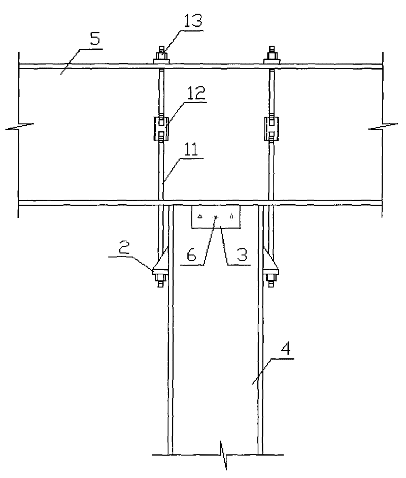
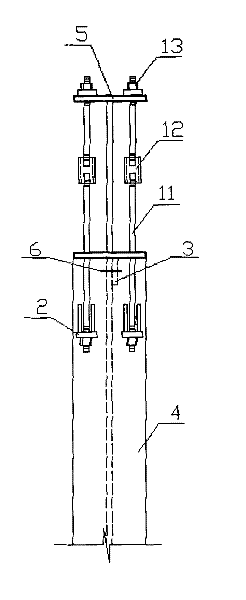
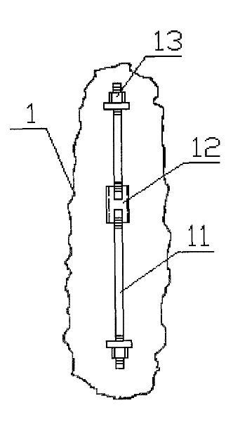

Embodiment 1

[0023] A prestressed steel structure connecting device of the present invention can be applied to such as Figure 6 The beam-to-column connection at node C is shown, where the beam at node C is a continuous member.

[0024] Figure 6 In the single-layer light steel portal frame shown, the beams and columns are welded H-shaped steel, the beam webs are placed vertically, and the column webs are placed along the beam length direction.

[0025] Such as figure 1 , figure 2 and image 3 As shown, the present invention is composed of a prestressed tie rod pair 1, a composite gusset plate 2, a shear key 3, a steel column 4 and a steel beam 5.

[0026] The prestressed tie rod pair 1 is formed by connecting two sections of steel tie rods 11 with threads at both ends through front and back buckle sleeves 12, and the steel tie rods 11 are high-strength round steel.

[0027] The combined gusset plate 2 is composed of three steel plates, one is a rectangular steel plate, and the other...

Embodiment 2

[0032] Figure 4 , Figure 5 The connection shown is suitable for use with Figure 6 The splicing node of components shown in node B is a special case of the present invention. Figure 6 In the single-layer light steel portal frame shown, the beam is welded H-shaped steel, and the beam web is placed vertically.

[0033] Such as image 3 , Figure 4 and Figure 5 As shown, the present invention is applied to a special case of component splicing, which is composed of a prestressed tie rod pair 1 , a combined gusset plate 2 , a shear key 3 and a steel beam 5 .

[0034] The prestressed tie rod pair 1 is formed by connecting two sections of steel tie rods 11 with threads at both ends through front and back buckle sleeves 12, and the steel tie rods 11 are high-strength round steel.

[0035] The combined gusset plate 2 is composed of three steel plates, one is a rectangular steel plate, and the other two are right-angled triangular steel plates. .

[0036] The prestressed tie...


PUM


Abstract

The invention discloses a steel structure connecting device applying prestress; the device consists of prestressed pull rod pairs, combined gusset plates, shear keys, steel columns and steel girders. The steel girders are vertically placed at the upper end of the steel columns to webplates being arranged in the length direction of the steel girders; combined gusset plates are fixedly connected atthe external sides of two flanges at the upper tips of the steel columns; the prestressed pull rod pairs penetrate the upper flanges and the lower flanges of the steel girders and holes arranged on the combined gusset plates, one end of each prestressed pull rod pair is connected at the upper flanges of the steel girders, and the other end is connected on the combined gusset plates; the shear keys are connected with the webs and the lower flanges of the steel girders. When in installation, the prestressed pull rod pairs are firstly installed, then the prestress is applied, and the shear keys are finally installed. The prestressed steel pull rods which are arranged in pairs are adopted to resist bending and the shear keys are adopted to resist shearing, the structure is clear, the construction is convenient, the materials are saved, and the connecting device is especially suitable for monolayer lightweight steel constructions.

Description

technical field [0001] The invention belongs to the technical field of building steel structure component connection, and more specifically relates to a steel structure connection device for applying prestress. Background technique [0002] Steel structures are widely used in various buildings. They are green structures, and the country encourages their active promotion and application. At present, the connection form of steel structure nodes in engineering is relatively simple, and bolt-welding hybrid or high-strength bolt connection is mostly used. Both of them require end plates whose thickness is much larger than that of component plates. The welds or bolts are more expensive and the construction is relatively complicated. Therefore, The cost of connecting nodes occupies a considerable proportion of the total project cost. Contents of the invention [0003] The purpose of the present invention is to solve the deficiencies in the above-mentioned existing steel structur...

Claims


Application Information

Patent Timeline
Patent Type & Authority Patents(China)
IPC IPC(8): E04B1/24
Inventor 唐柏鉴蒋志勇
Owner GUANGDONG UNION STEEL MFG
Learn More