Floating-type cushion cylinder

A buffer oil cylinder and floating technology, applied in the field of hydraulic oil cylinders, can solve the problems that the buffer gap cannot be designed too small, the buffer effect is not good, and the automatic alignment cannot be achieved, and the effect of simple structure, strong practicability, and collision prevention can be achieved.

Active Publication Date: 2009-12-09
JIANGSU HENGLI HYDRAULIC
View PDF0 Cites 22 Cited by
  • Summary
  • Abstract
  • Description
  • Claims
  • Application Information

AI Technical Summary

Problems solved by technology

In the previous structure, the buffer plunger and the buffer hole are generally fixed and cannot be automatically centered. Due to the inevitable machining error, the buffer gap cannot be designed too small, otherwise it is easy to get stuck, so the buffer effect is not good; In some cases, a floating buffer sleeve is added outside the buffer plunger for automatic centering, but the buffer sleeve needs to be quenched or nitrided to improve the surface hardness, resulting in a long processing cycle and high cost

Method used


Image

  • Floating-type cushion cylinder
  • Floating-type cushion cylinder
  • Floating-type cushion cylinder

Examples


Embodiment Construction

[0017] The present invention will now be further described in conjunction with the accompanying drawings and preferred embodiments. These drawings are all simplified schematic diagrams, which only illustrate the basic structure of the present invention in a schematic manner, so they only show the configurations related to the present invention.

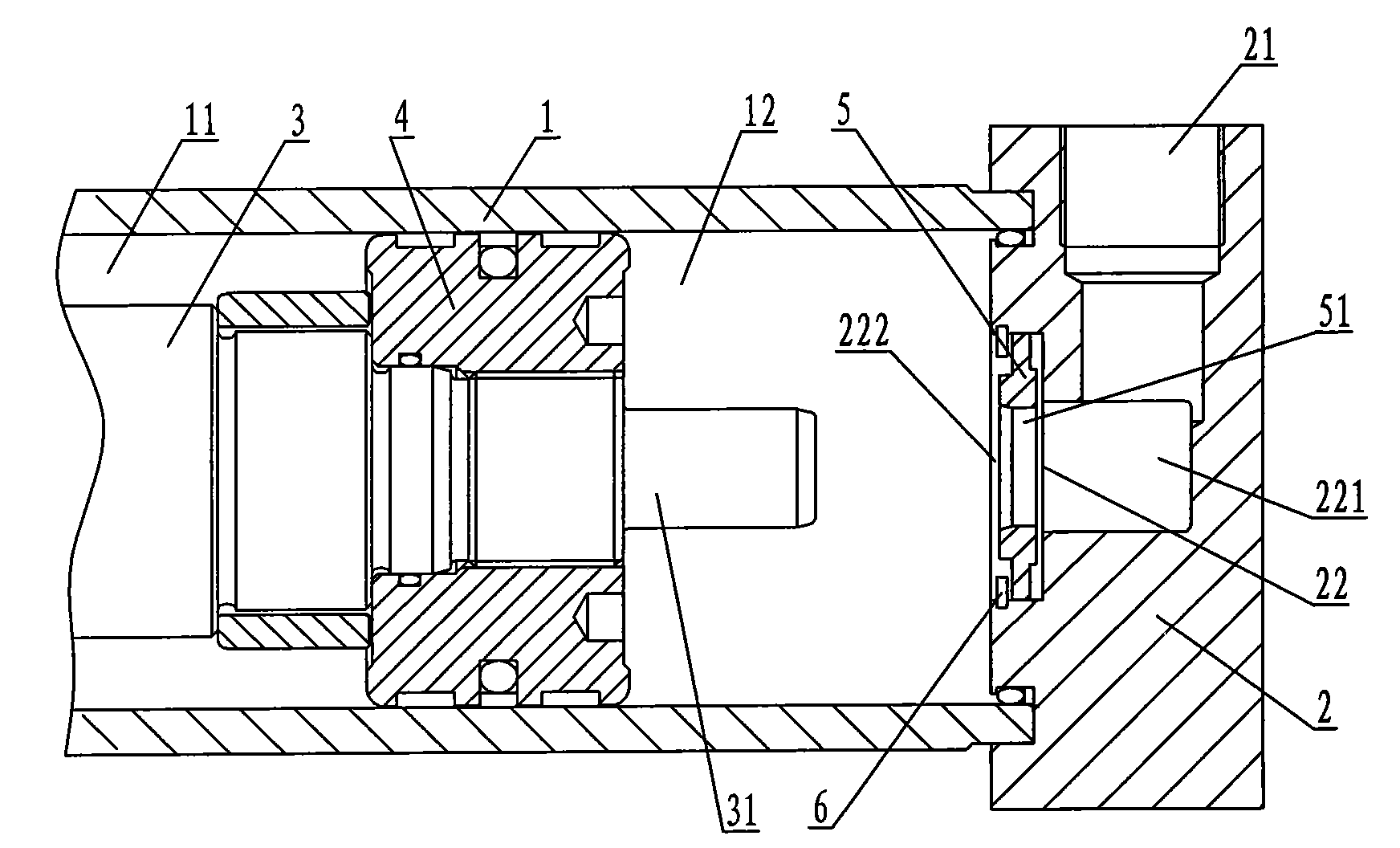
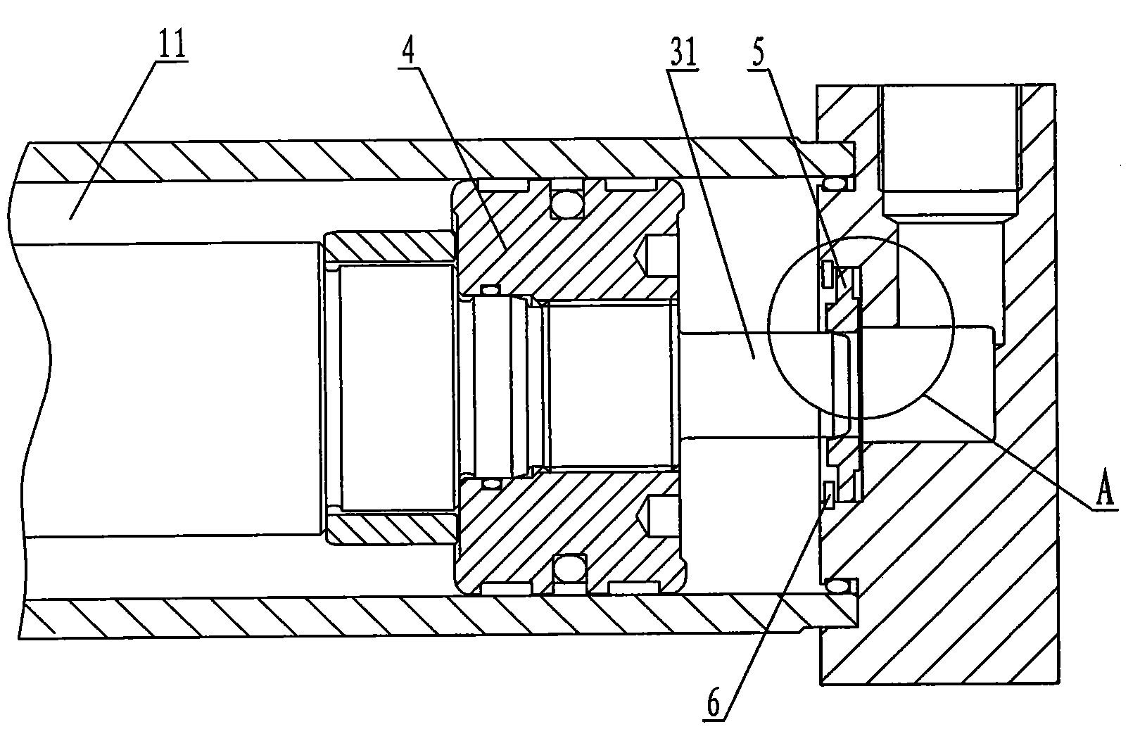
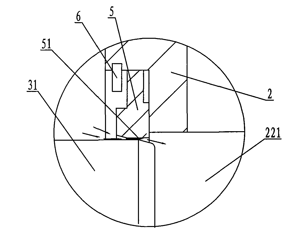
[0018] Such as Figure 1 to Figure 6 The specific structure of a floating buffer oil cylinder shown includes a cylinder barrel 1, a cylinder bottom cover 2, a piston rod 3 and a piston 4, and the extension direction of the piston rod 3 is set to the front, and vice versa to the rear. The cover 2 is fixed on the rear end of the cylinder 1, the piston 4 is fixed on the rear end of the piston rod 3, the outer circle of the piston 4 is liquid-tight with the inner circle of the cylinder 1, and the piston 4 divides the inner cavity of the cylinder 1 into a rod cavity 11 and a There is no rod cavity 12, and the cylinder bottom cover 2 is pr...


PUM


Abstract

The invention discloses a floating-type cushion cylinder, comprising a cylinder barrel, a cylinder bottom head, a piston rod and a piston; wherein, the piston rod is extended back to front; a back end surface of the piston rod is provided with a cushion plunger which is in integral structure with the piston; the cylinder bottom head is provided with stepped holes which are located on the same axes with the piston rod; the diameter of a small hole of the stepped holes is larger than the external diameter of the piston rod, while a big hole of the stepped holes is internally provided with a cushion collar and an internal circlip which is used for preventing the cushion collar from sliding out in a floating manner; the cushion collar is provided with a cushion hole; a cushion gap is formed between the excircle of the cushion plunger and the cushion hole after the cushion plunger is driven by hydraulic oil to enter into the cushion hole. In the invention, the cushion collar is designed in a floating type, so when entering into the cushion hole, the cushion plunger can be automatically centered to reduce the cushion gap, thus having better cushion effect, effectively preventing striking when the cylinder cushion retracts to the cylinder bottom; and the cylinder has fine initiation. The invention is simple in structure and strong in practicability.

Description

technical field [0001] The invention relates to the field of hydraulic oil cylinders, in particular to a floating buffer oil cylinder which can prevent the impact of the oil cylinder piston when it retracts to the bottom of the cylinder. Background technique [0002] Generally, the buffer structure design used in hydraulic cylinders is to process a buffer plunger on the piston rod. When the piston retracts to the bottom of the cylinder, the buffer plunger retracts into the buffer hole. The gap between the buffer hole and the buffer plunger is very small, so that the hydraulic pressure The oil return of the cylinder produces a throttling effect and produces back pressure, thereby playing a buffering role. The buffering effect is determined by the gap between the buffering plunger and the buffering hole. In the previous structure, the buffer plunger and the buffer hole are generally fixed and cannot be automatically centered. Due to the inevitable machining error, the buffer g...

Claims


Application Information

Patent Timeline
Patent Type & Authority Applications(China)
IPC IPC(8): F15B15/14F15B15/22
Inventor 汪立平
Owner JIANGSU HENGLI HYDRAULIC
Why Eureka
Try Eureka