Thermo-compensation current sensing head as well as alternate current measurement method and system

A technology of temperature compensation and alternating current, applied in the direction of measuring current/voltage, thermometers, measuring devices, etc., can solve the problems of optical fiber birefringence, vibration and bending, and affect sensor performance, etc., to achieve good electrical insulation, low cost, Effects of Improving Sensitivity and Range

Inactive Publication Date: 2012-01-04
ZJMECH TECH +1
View PDF4 Cites 0 Cited by
  • Summary
  • Abstract
  • Description
  • Claims
  • Application Information

AI Technical Summary

Problems solved by technology

Since the sensing beam and the reference beam of the optical fiber current sensor with this structure are transmitted in two optical fibers, the interference of birefringence, ambient temperature, vibration, bending and other factors inside the optical fiber will seriously affect the performance of the sensor.
The sensing beam and reference beam of the FPI fiber optic current sensor are transmitted in the same optical fiber, which effectively solves the problems of birefringence, vibration and bending of the optical fiber, but the influence of temperature cannot be solved.

Method used


Image

  • Thermo-compensation current sensing head as well as alternate current measurement method and system
  • Thermo-compensation current sensing head as well as alternate current measurement method and system
  • Thermo-compensation current sensing head as well as alternate current measurement method and system

Examples


Embodiment 1

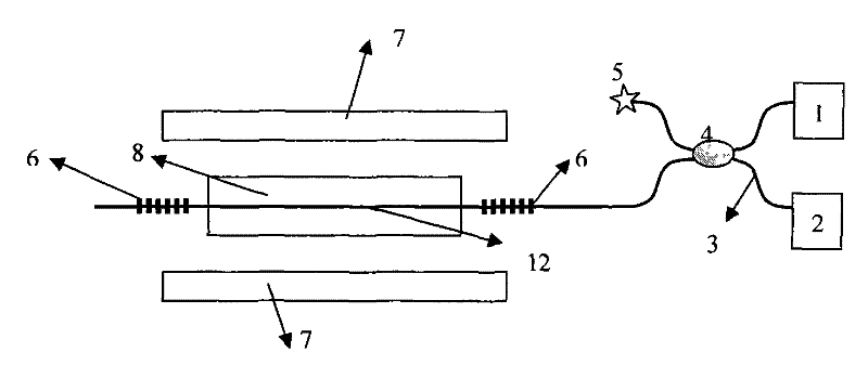
[0028] Embodiment 1: see attached figure 1 , is a structural schematic diagram of the fiber grating FPI current measuring device. The fiber grating FPI12 is pasted on the magnetostrictive material 8, and the permanent magnet 7 is fixed on both sides of the magnetostrictive material 8 in parallel. The refractive index matching liquid 5 is connected, and the two ports on the other side of the fiber coupler 4 are respectively connected with the monochromatic light source 1 and the photodetection device 2 .

[0029] The F-P cavity of the fiber grating FPI12 is constrained by the magnetostrictive material 8, and the two fiber grating parts 6 are placed freely; the reflectivity of the fiber grating FPI12 is less than 5%.

[0030] The monochromatic light source emits a wavelength of λ and a light intensity of I 0 The optical signal is transmitted to the fiber grating FPI sensor probe through the coupler. Since the reflectivity of the fiber grating FPI is less than 5%, the reflecte...

Embodiment 2

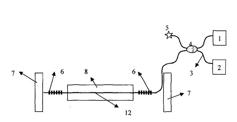
[0045] Embodiment 2: see attached figure 2 , the difference from Embodiment 1 is that the two permanent magnets 7 are respectively fixed at both ends of the magnetostrictive material.

Embodiment 3

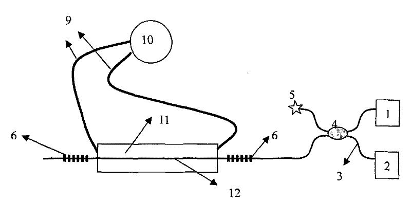
[0046] Embodiment 3: see attached image 3 , the difference from Embodiment 1 is that the driving element that makes the cavity length of the fiber grating FPI12 vary periodically includes a transmission line 9 , a piezoelectric ceramic 11 and a mutual induction coil 10 . The output of the mutual induction coil 10 is connected to the piezoelectric ceramic 11 through the transmission line 9 .

[0047] The mutual induction coil converts the current in the busbar into a voltage, and loads it on the piezoelectric ceramic through the transmission line. Driven by the voltage, the piezoelectric ceramic deforms and acts on the F-P cavity of the fiber grating, causing the F-P cavity of the fiber grating to deform.

[0048] The realization device of this method is that the fiber grating FPI of the fiber grating Fabry-Perot interferometer is pasted on the magnetostrictive material, and it is connected with a port of the fiber coupler through a single-mode fiber, and the monochromatic li...


PUM

PropertyMeasurementUnit
wavelengthaaaaaaaaaa
reflectanceaaaaaaaaaa

Abstract

The invention relates to a thermo-compensation current sensing head as well as an alternate current measurement method and a system thereof. A current sensing head is placed in a magnetic field generated by alternate current to be measured, and a fiber bragg grating FPI adhered on magnetostrictive material senses ambient temperature and magnetic induction. A light signal emitted by a monochromatic light source enters fiber bragg grating F-P cavity of a fiber bragg grating Fabry-Perot interferometer and forms a similar two beam light interference signal after interference to be output. Cavity length variation amount of the fiber bragg grating F-P cavity of the fiber bragg grating Fabry-Perot interferometer is obtained according to the two beam interference signal, and then alternate current measurement value is obtained according to the cavity length variation amount. And finally, compensation relation between current measurement value and actual value to be measured on temperature is utilized to obtain alternate current actual value. The performance of an original current sensor is improved, preparation technology is relatively simple, and simultaneous measurement of temperature and alternate current can be realized.

Description

technical field [0001] The invention relates to a temperature-compensated current sensor head and an alternating current measurement method and system, belonging to the field of optical fiber sensing and optical measurement. Background technique [0002] The principle of the fiber grating sensor is to convert the measured value into the drift of the fiber grating Bragg wavelength. It is simple to manufacture, but its wavelength modulation characteristic brings certain difficulties to signal demodulation. Ordinary fiber optic Fabry-Perot interferometer (FPI) sensor utilizes the principle of optical fiber light transmission and F-P interference, and has high measurement accuracy, but the manufacturing process is relatively difficult. Fiber Bragg grating FPI is composed of two identical fiber gratings written in the same fiber, which combines the advantages of fiber Bragg grating and fiber FPI. The advantages of the all-fiber structure can reach the measurement accuracy of the...

Claims


Application Information

Patent Timeline
Patent Type & Authority Patents(China)
IPC IPC(8): G01R19/00G01R15/24G01K11/32G01K11/3206
Inventor 赵建林吕全超姜碧强
Owner ZJMECH TECH
Why Eureka
Try Eureka