Capacitive acceleration detector intermediate movable electrode

A technology of acceleration and geophones, which is applied in the field of capacitive acceleration geophones, can solve the problems of affecting the strength of support beams, easily forming stress concentration, and poor consistency of capacitance, so as to achieve good capacitance consistency, not easy to deform and break, and not Easy stress concentration effect

Inactive Publication Date: 2009-12-09
WEIHAI SUNFULL ELECTRONICS GRP CO LTD
View PDF1 Cites 2 Cited by
  • Summary
  • Abstract
  • Description
  • Claims
  • Application Information

AI Technical Summary

Problems solved by technology

[0003] The technical problem solved by the present invention is to solve the problem that the manufacturing process of the L-shaped support beam is complex, the cost is high, and the stress concentration is easily formed during the production process, which affects the strength of the support beam, easily causes deformation and fracture, and causes poor consistency of capacitance, large noise, and poor performance. Stability, large waveform distortion, and even damage to the geophone, provide a simple manufacturing process, low cost, not easy to form stress concentration in the production process, not easy to cause deformation and fracture, good capacitance consistency, low noise, stable performance, Movable electrode in the middle of capacitive acceleration detector with small waveform distortion

Method used


Image

  • Capacitive acceleration detector intermediate movable electrode
  • Capacitive acceleration detector intermediate movable electrode
  • Capacitive acceleration detector intermediate movable electrode

Examples


Embodiment 1

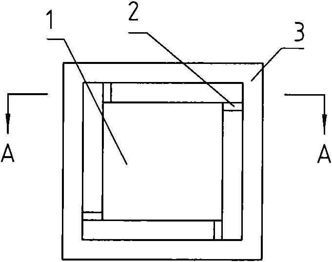
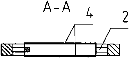
[0025] Such as figure 1 , figure 2 The movable electrode in the middle of the capacitive acceleration detector is provided with a mass block 1, and a support beam 2 is uniformly distributed on the mass block 1, and the support beam 2 is connected to the inner side of the frame 3. 2 is a straight support beam. The support beam 2 is located at the corner of the mass block 1 and is perpendicular to the mass block 1 and the frame 3. The manufacturing process is simple and the cost is low. It is not easy to form stress concentration during the manufacturing process, and it is not easy to cause deformation and fracture. Good consistency, low noise, stable performance, and low waveform distortion.

Embodiment 2

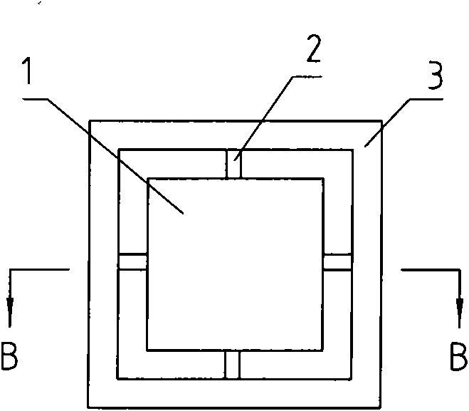
[0027] Such as image 3 , Figure 4 The movable electrode in the middle of the capacitive acceleration detector is provided with a mass block 1, and a support beam 2 is uniformly distributed on the mass block 1, and the support beam 2 is connected to the inner side of the frame 3. 2 is a straight support beam, the support beam 2 is located in the middle of the side of the mass block 1, perpendicular to the inner side of the mass block 1 and the frame 3, the manufacturing process is simple, the cost is low, and it is not easy to form stress concentration during the manufacturing process, and it is not easy to cause deformation and fracture. Capacitance consistency is good, noise is small, performance is stable, and waveform distortion is small.

Embodiment 3

[0029] Such as Figure 5 , Figure 6 The movable electrode in the middle of the capacitive acceleration detector is provided with a mass block 1, and a support beam 2 is uniformly distributed on the mass block 1, and the support beam 2 is connected to the inner side of the frame 3. 2 is a straight support beam. The support beam 2 is located on the sharp corner of the mass block 1 and the inner corner of the frame 3. The manufacturing process is simple and the cost is low. It is not easy to form stress concentration during the manufacturing process, and it is not easy to cause deformation and fracture. The capacitance consistency is good. Low noise, stable performance, and small waveform distortion.


PUM


Abstract

The invention provides a capacitive acceleration detector intermediate movable electrode, relating to a capacitive acceleration detector which is provided with a mass block, the mass block is evenly arranged with support beams; the support beams are connected with the inner sides of a frame; the mass block is provided with a metal plate and the support beams are straight. The invention has the advantages of simple manufacturing technology, low cost, good electric capacity consistency, low noise, stable performance, little wave distortion; the invention further has the advantages that in the manufacturing process, stress concentration can not easily be formed, and deformation and fracture cannot easily be caused, thus applicable to the capacitive acceleration detector.

Description

technical field [0001] The invention relates to a capacitive acceleration detector, in particular to a movable electrode in the middle of the capacitive acceleration detector. Background technique [0002] We know that the movable electrode in the middle of the existing capacitive acceleration detector, such as the patent No. 5652384 published by the U.S. Patent Office on July 29, 1997, is called a sensor with an L-shaped support beam structure. The movable electrode in the middle is provided with a mass The four sides of the mass block are provided with L-shaped support beams up and down correspondingly, and the upper and lower layers of eight L-shaped support beams are connected to the middle of the inner side of the frame, and the mass block is provided with metal plates. The movable electrode in the middle of the capacitive acceleration detector has L-shaped support beams corresponding to the four sides of the mass block, and the L-shaped support beams have 90° corners. ...

Claims


Application Information

Patent Timeline
Patent Type & Authority Applications(China)
IPC IPC(8): G01V1/18
Inventor 杨仲华唐晓刚张丽霞牛德芳
Owner WEIHAI SUNFULL ELECTRONICS GRP CO LTD
Why Eureka
Try Eureka