Combination heat sink of closed shell electronic equipment

A technology of electronic equipment and airtight casing is applied in the field of combined heat dissipation of electronic equipment, which can solve the problems of elevated ambient temperature, no maintenance of radiated components, PCB board replacement, inconvenient maintenance, etc., and achieves convenient replacement. Effect

Active Publication Date: 2009-12-09
KYLAND TECH CO LTD
View PDF0 Cites 16 Cited by
  • Summary
  • Abstract
  • Description
  • Claims
  • Application Information

AI Technical Summary

Problems solved by technology

[0002] Electronic equipment such as industrial and military switches, servers, and cabinets are restricted by harsh environments, and often require a closed structure for the housing; during the operation of the equipment, components such as switching chips and power modules will generate heat, which will increase the internal temperature of the equipment and affect the electronics. Component life and performance
The traditional implementation method is that the heat of the chip is conducted to the heat dissipation fins of the casing through the internal heat conduction device to dissipate heat; the heat dissipation effect is limited, and it is inconvenient to replace and maintain the PCB board
Chinese patent authorization number CN2599502Y, authorized announcement date January 14, 2004, the name of the utility model is heat pipe type airtight radiator, the authorized patent discloses that by improving the layout of the radiator, relying on the efficacy of individual components to improve the efficiency of the airtight electric control cabinet Heat exchange and heat dissipation efficiency, the disadvantage is that it does not involve the maintainability of the heat dissipation device, and cannot control the heat dissipation effect of the heat dissipation device

Method used


Image

  • Combination heat sink of closed shell electronic equipment
  • Combination heat sink of closed shell electronic equipment
  • Combination heat sink of closed shell electronic equipment

Examples


Embodiment Construction

[0016] The present invention will be further described below in conjunction with the accompanying drawings.

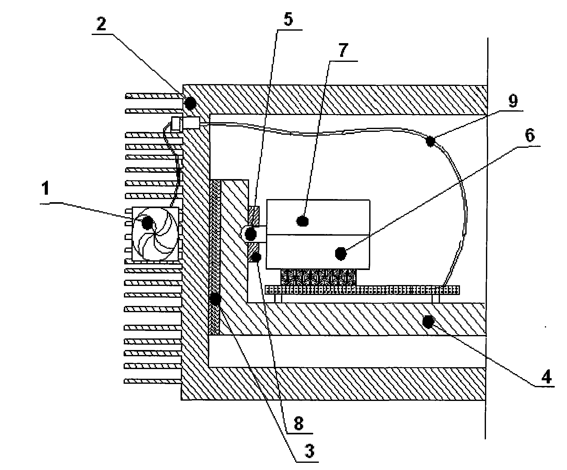
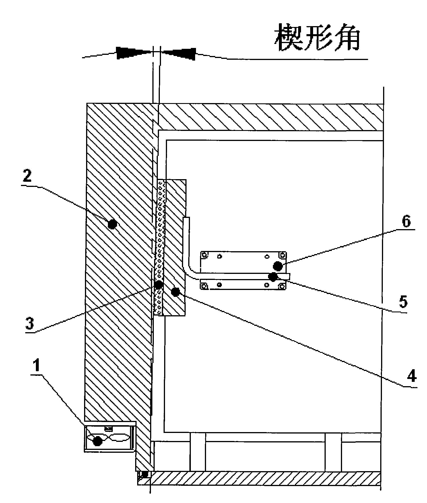
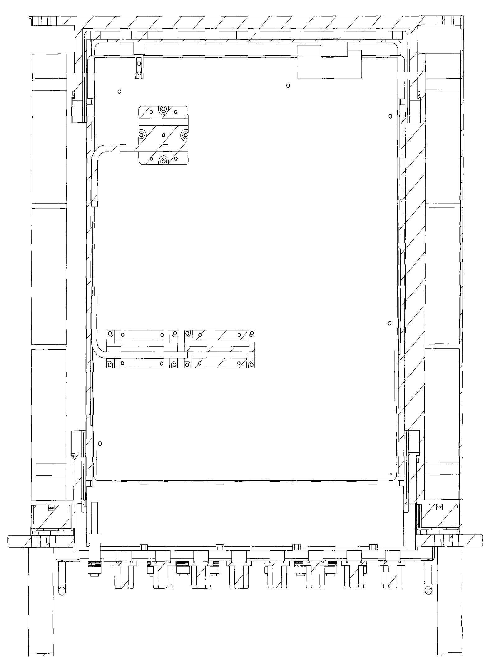
[0017] figure 1 Front view of combined cooling device structure, figure 2 The top view of the structure of the combined heat sink indicates that the combined heat sink consists of a fan 1 , a housing with heat sink 2 , a heat conduction film 3 , a PCB fixing bracket 4 , a heat pipe 5 , and a chip heat conduction plate 6 . The above six components are divided into the internal chip heat conduction component part and the external heat dissipation device part. The internal chip heat conduction component part is composed of heat pipe 5, chip heat conduction plate 6, PCB fixing bracket 4, and heat conduction film 3. Heat pipe fixing plate 8 is fixed. The external cooling device part is composed of a fan 1 and a housing 2 with cooling fins. The PCB fixing bracket 4 , the heat pipe fixing plate 7 at the chip end, the heat pipe fixing plate 8 at the heat dissipation end, ...


PUM


Abstract

The invention discloses a combination heat sink of a fan, heat pipe and the like of closed shell electronic equipment, aiming at solving the conflict between high protection grade and excellent heat dissipation required by the closed shell electronic equipment. The key of the technical proposal is as follows: the combination heat sink of the closed shell electronic equipment comprises the structures of the fan, the shell with heat sinks, a heat conduction film, a PCB fixed bracket, a heat conducting pipe and a chip heat conducting plate. The heat conducting pipe connects the chip heat conducting plate and the PCB fixed bracket, the vertical section shape of the side plate of the PCB fixed bracket is of wedge shape, the wedge-shaped face is in tight contact with the inner wall of the shell, the inner side of the shell and the matching face of the side plate of the PCB fixed bracket are inclined planes with the same angle, the heat conduction film is arranged between the contact faces to ensure the tight contact between the PCB fixed bracket and the inner wall of the shell; the outer shell side of the shell is platy heat dissipation structure; the end of the heat sinks is fixed with the fan to form an air passage, thus providing air cooling and convection heat dissipation for the heat sinks. The invention is suitable for the heat dissipation of the closed shell electronic equipment.

Description

technical field [0001] The invention relates to the technical field of combined heat dissipation of electronic equipment, and more specifically, relates to a combined heat dissipation device of a fan and a heat pipe of an electronic equipment with a closed casing. Background technique [0002] Electronic equipment such as industrial and military switches, servers, and cabinets are restricted by harsh environments, and often require a closed structure for the housing; during the operation of the equipment, components such as switching chips and power modules will generate heat, which will increase the internal temperature of the equipment and affect the electronics. Component life and performance. The traditional implementation method is that the heat of the chip is conducted to the heat dissipation fins of the casing through the internal heat conduction device to dissipate heat; the heat dissipation effect is limited, and it is inconvenient to replace and maintain the PCB bo...

Claims


Application Information

Patent Timeline
Patent Type & Authority Applications(China)
IPC IPC(8): H05K7/20H01L23/34H01L23/467
Inventor 王敬文薛百华陈凡民郑国庆吴立群
Owner KYLAND TECH CO LTD
Why Eureka
Try Eureka