Pitch of blades on a wind power plant

A blade and pitch technology, applied in the field of controlling this kind of wind power station, to achieve the effect of reducing thrust impact, increasing possibility, and reducing thrust impact

Active Publication Date: 2009-12-09
LM GLASSFIBER
View PDF1 Cites 5 Cited by
  • Summary
  • Abstract
  • Description
  • Claims
  • Application Information

AI Technical Summary

Problems solved by technology

This stall interrupts the lifting of the blade

Method used


Image

  • Pitch of blades on a wind power plant
  • Pitch of blades on a wind power plant
  • Pitch of blades on a wind power plant

Examples


Embodiment Construction

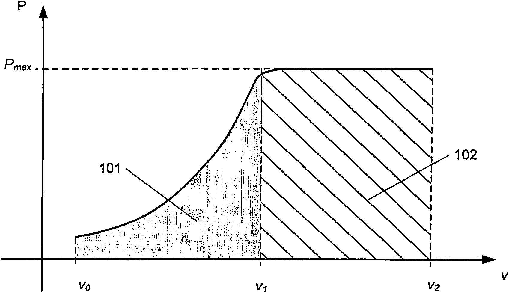
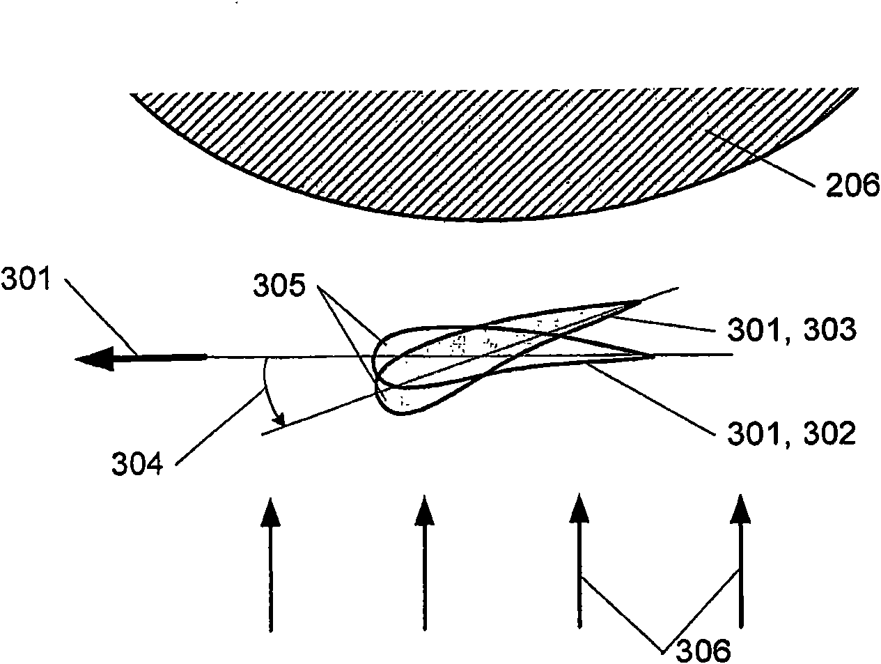
[0037] figure 1 A typical output curve of a wind power plant is schematically shown. The curve shows the power P obtained as a function of wind speed V. A wind power station with speed v 0 In the case of pitch regulation and active stall regulation pitch, a pitch of 5° is usually used to start the rotor. Here and in the following, the positive pitch angle is defined by the leading edge of the blade profile, see also Figure 3 below for a more detailed depiction. From there, the power output increases with increasing wind speed until the wind speed increases to a speed v 1 . Within this range 101 the wind power plant is configured to maximize the power and productivity produced by the wind power plant. at wind speed v 1 When , the wind power station produces the maximum power P max . speed v 1 The size of is dependent on various factors, such as economic factors, including eg the size of the generator and the wind conditions at the location where the wind power plant is...


PUM


Abstract

The present invention relates to a blade for a wind power plant with an assembly face for mounting in a circular pitch bearing, whose pitch axis is angled relative to the longitudinal axis of the blade, and wherein the blade comprises a root part with an approximately elliptic cross-section, in which root part the assembly face is arranged. The invention further relates to a wind power plant in general having a pitch- adjustable blade mounted in a pitch bearing such that the distance between the outermost part of the blade and the tower is increased when the leading edge of the blade is pitched up in the wind. This is accomplished in that the longitudinal axis of the blade is angled in a particular way compared to its pitch axis. The invention also relates to a method of controlling a wind power plant, including to increase the rotor area and / or increasing the distance between the outermost part of at least one blade and the tower by regulating, during operation, the pitch of a blade about a pitch axis which is angled relative to the longitudinal axis of the blade.

Description

technical field [0001] The invention relates to blades of a wind power plant and to a wind power plant comprising a tower and a rotor with a plurality of blades, wherein at least one blade is mounted in a pitch-adjustable manner on a pitch bearing. Furthermore, the invention also relates to a method of controlling such a wind power plant. Background technique [0002] The electrical output achievable by a wind power plant depends directly on the size of the rotor swept area (rotorarea) and thus on the effective length of the blades. As a rule of thumb, a 1% shortening of the blades will result in a 2-3% reduction in power output. In order to save material and weight, the blades of wind power plants are usually very flexible, so the bending caused by the wind is very easy to understand. It follows from this that the deformation of the blades leads to a reduction in the swept area of ​​the rotor and thus to an undesired reduction in power output. [0003] Furthermore, the d...

Claims


Application Information

Patent Timeline
Patent Type & Authority Applications(China)
IPC IPC(8): F03D1/06F03D7/02F03D11/00
CPCF05B2270/33F03D1/0658Y02E10/723F03D7/042F03D7/0224F03D7/0288F03D7/0236F05B2250/314Y02E10/722Y02E10/72F05B2260/70F05B2270/17F05B2250/14Y02E10/721F05B2260/74F03D80/00F03D7/022F03D7/0244
Inventor T·瑟伦森
Owner LM GLASSFIBER
Why Eureka
Try Eureka