Method for removing obstruction of atomizer

A technology of atomizer and blockage, applied in the direction of injection device, etc., can solve the problems of easily damaged inner tube, poor cleaning effect, long time consumption, etc., and achieve the effect of high safety, efficiency and good use effect.

Inactive Publication Date: 2009-12-16
PANGANG GROUP RESEARCH INSTITUTE CO LTD +2
View PDF0 Cites 11 Cited by
  • Summary
  • Abstract
  • Description
  • Claims
  • Application Information

AI Technical Summary

Problems solved by technology

Especially in the field of metallurgical analysis, due to the diversity, complexity, difficulty of digestion, and easy hydrolysis of the samples submitted for inspection in the metallurgical industry, it is often necessary to digest samples by high-temperature melting of alkaline fluxes, which will inevitably produce many samples such as test solution. Unfavorable factors such as high salt concentration and unmelted sample residues that easily lead to nebulizer blockage
Concentric nebulizers are easily clogged due to salting out or insoluble particles, which may affect the accuracy of test results in severe cases, or cause damage to the nebulizer until it is scrapped (a nebulizer is about 600-800 US dollars)
Concentric atomizers are mostly made of fragile silicon glass or quartz materials. The main methods for removing blockages are as follows: ① Use a special cleaning device for the atomizer, but you need to purchase expensive equipment; ② Remove the atomizer and turn the nozzle upward Knocking loosens the blockage and discharges the capillary under the action of gravity, but most of them have no effect and are easy to damage the inner tube; ③ Connect compressed air to the nozzle for back blowing, but an air compressor is required to provide a compressed air source, which is relatively difficult to implement Difficult; ④ inhale 5% hydrofluoric acid (HF) to clean, but because HF has strong toxicity, it is easy to corrode the atomizer, and the detection results of Si elements are high; ⑤ immerse the nozzle in concentrated nitric acid (HNO 3 ) and heated to above 100°C to remove, but due to the structure of the nozzle, the blockage cannot effectively contact and fully react with nitric acid, which takes too long and the removal effect is poor; ⑥Blow the solvent into the inner tube with a dropper or a washing bottle, Inability to achieve the desired effect due to insufficient pressure
All of the above cleaning methods need to disassemble the nebulizer from the instrument. If it is disassembled or installed improperly, it will easily damage the nozzle or capillary inner tube, so it has many disadvantages.

Method used


Image

  • Method for removing obstruction of atomizer
  • Method for removing obstruction of atomizer
  • Method for removing obstruction of atomizer

Examples


Embodiment 1

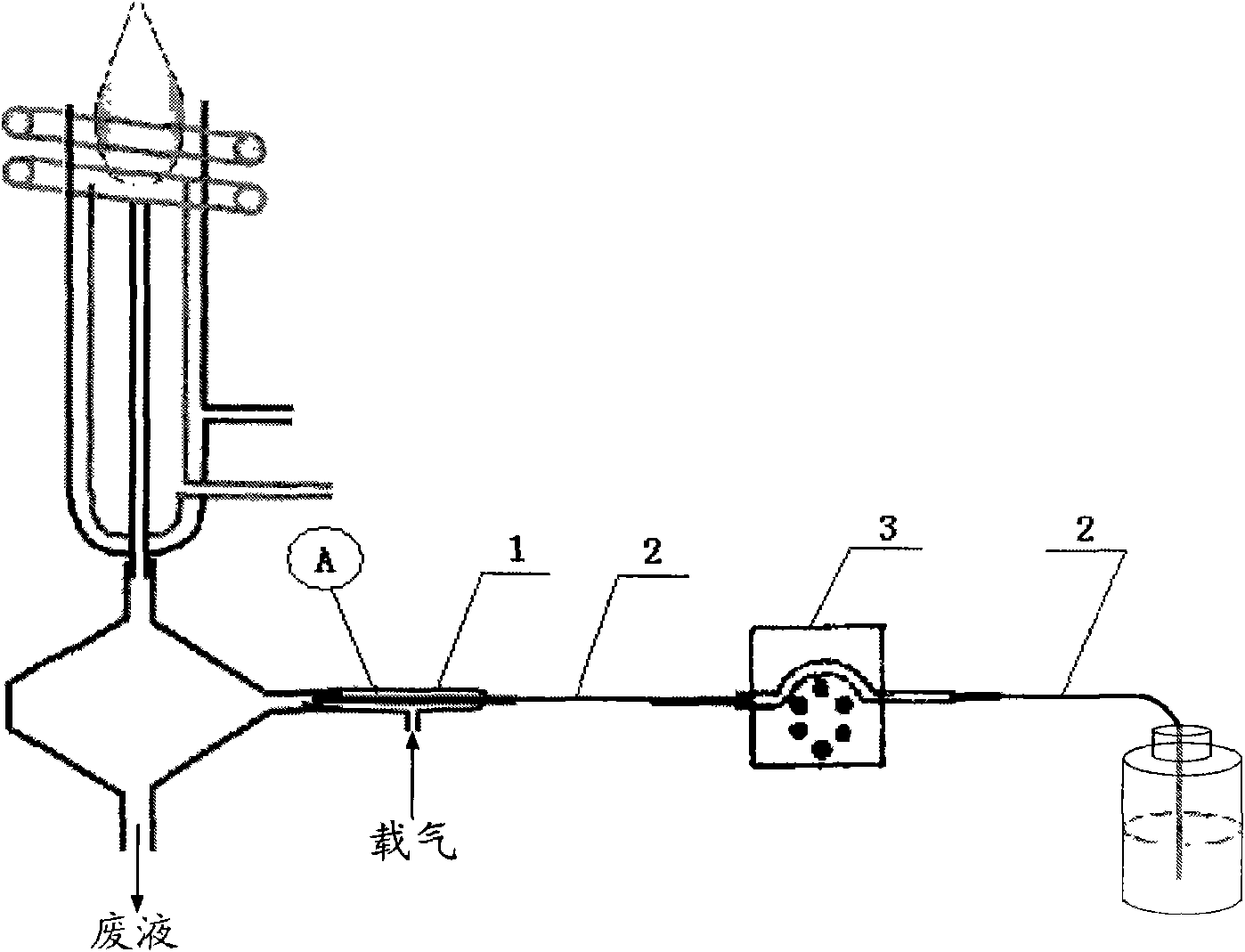
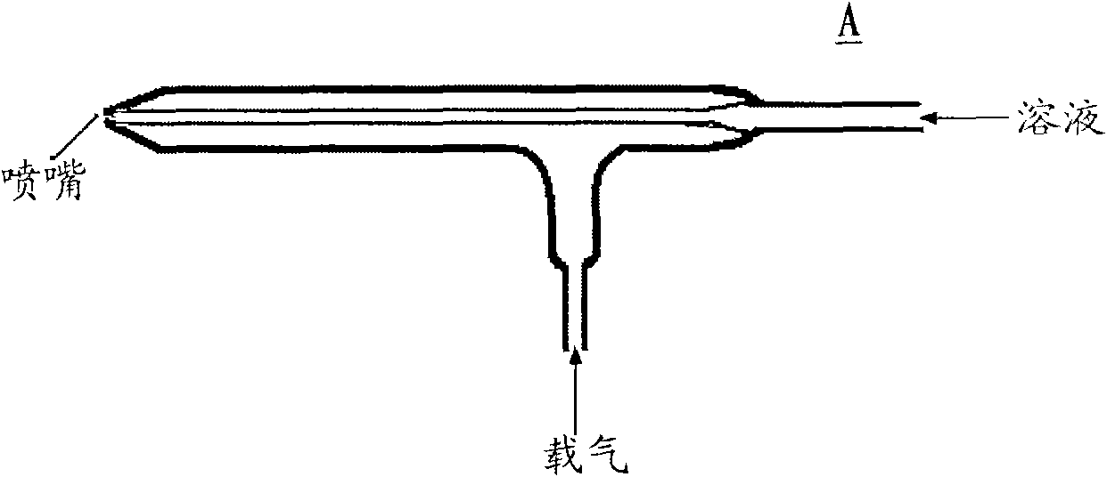
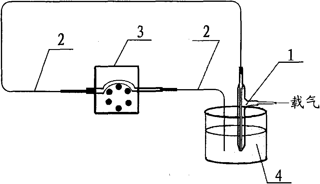
[0030] Embodiment 1, with reference to figure 1 , figure 2 and image 3 .

[0031] The first technical solution of the present invention is a method for removing blockages in an atomizer by using a cleaning solution. The technical solution is to use the atomizer 1, the sampling capillary inner tube 2, the peristaltic pump 3 and the connecting pipeline on the original equipment in the original normal working connection state to replace the original sample solution with a cleaning solution. A method of removing clogs by using solution 4. Use the following cleanup methods during operation:

[0032] The composition of the blockage (or sample) is: determined by Na 2 CO 3 、HBO 3 V of mixed alkaline reagent melt digestion 2 o 5 blockages generated during the sample solution; first pull out the atomizer 1 from the atomization chamber of the original testing instrument, and put the nozzle end of the atomizer into the container containing the cleaning solution 4; choose 25mL f...

Embodiment 2

[0034] On the basis of embodiment 1, the component of embodiment 2 blockage (or sample) is: measure with Li 2 B4 o 7 For the blockage produced when melting and digesting the steel alloy sample solution, 30mL concentrated hydrochloric acid (HCl) and 10mL concentrated nitric acid (HNO 3 ), then add 90mL of distilled water and mix evenly, and heat the mixed solution to 50°C; the rotation speed of the peristaltic pump 3 is 120 rpm, and use the peristaltic pump 3 to squeeze the cleaning solution 4 into the inlet of the atomizer 1. Sample capillary inner tube 2, set the pressure of the atomizing airflow to 25psi; blow atomizing airflow into the atomizer 1, make the cleaning solution 4 pass through the sampling capillary inner tube 2 at a high speed under the negative pressure generated by the high-speed airflow Spray from one end of the atomizer nozzle, so as to wash and clean the blockage in the atomizer at a high speed, so that the cleaning solution can fully and effectively cont...

Embodiment 3

[0036] On the basis of embodiment 1, the component of embodiment 3 blockage (or sample) is: measure with K 2 S 2 o 7 For the blockage produced when the ore sample solution is melted and digested, 40mL of concentrated hydrochloric acid (HCl) and 20mL of concentrated nitric acid (HNO 3 ), then add 100mL of distilled water and mix evenly; the rotation speed of the peristaltic pump 3 is 160 rpm, use the peristaltic pump 3 to squeeze the cleaning solution 4 into the sampling capillary inner tube 2 inside the nebulizer 1, and use the mist The pressure of the atomizing air flow is 40 psi; the atomizing air flow is blown into the atomizer 1, so that the cleaning solution 4 passes through the sampling capillary inner tube 2 at a high speed under the negative pressure generated by the high-speed air flow and is ejected from one end of the atomizer nozzle. In this way, the blockage in the atomizer is washed and cleaned at a high speed, so that the cleaning solution and the blockage can...


PUM


Abstract

The invention discloses two methods of removing obstruction of a concentric atomizer, one of which comprises using a cleaning solution to remove obstruction in the atomizer, putting one end of a nozzle of the atomizer into the cleaning solution, blowing atomizing flow into the atomizer, so as to enable the cleaning solution to pass through a sampling capillary tube at high speed under negative pressure function produced by high speed gas flow and spray from the nozzle of the atomizer, thereby brushing and cleaning the obstruction in the atomizer at high speed; the other comprises using atomizing gas flow for back flushing of obstruction in the atomizer, plugging the gas flow channel of the atomizer, connecting one end of the nozzle of the atomizer with an atomizing gas flow pipeline, using high speed gas flow for back flushing of the sampling capillary tube from the nozzle end of the atomizer, so as to brush and clean the obstruction in the atomizer at high speed. In the case of maintaining original connection state of the atomizer unchanged, the invention meets the requirement of removing obstruction in the atomizer, reduces the frequency of replacing the atomizer as a result of blocking damage, and greatly reduces the production cost.

Description

technical field [0001] The invention relates to the field of maintenance and repair of analytical instruments, in particular to a method for efficiently and conveniently removing blockages of concentric nebulizers used in analytical instruments. Background technique [0002] The concentric pneumatic nebulizer is a key component of detection and analysis equipment, and its unique structure makes it extremely easy to be damaged due to blockage. The maximum gap between the nozzles is 0.03mm, and the blockage cannot fully and effectively contact and react with the cleaning liquid. Therefore, clearing clogging is a common problem for concentric pneumatic atomizers. Especially in the field of metallurgical analysis, due to the diversity, complexity, difficulty of digestion, and easy hydrolysis of the samples submitted for inspection in the metallurgical industry, it is often necessary to digest samples by high-temperature melting of alkaline fluxes, which will inevitably produce ...

Claims


Application Information

Patent Timeline
Patent Type & Authority Applications(China)
IPC IPC(8): B05B15/02
Inventor 成勇
Owner PANGANG GROUP RESEARCH INSTITUTE CO LTD
Why Eureka
Try Eureka