Vibration waveform controlling system of electro-hydraulic exciter

A technology of vibration waveform and electro-hydraulic excitation, which is applied in the direction of electrical program control, vibration test, and feedback control, can solve the problems of large output waveform distortion, small output waveform distortion, and low precision, and achieve control accuracy high effect

Inactive Publication Date: 2009-12-16
ZHEJIANG UNIV OF TECH
View PDF0 Cites 23 Cited by
  • Summary
  • Abstract
  • Description
  • Claims
  • Application Information

AI Technical Summary

Problems solved by technology

[0005] In order to overcome the deficiencies of large output waveform distortion and low precision of the existing vibrator output waveform control system, the present invention provides an electro-hydraulic vibrator that adopts closed-loop control, has low output waveform distortion and high control precision Vibration Waveform Control System

Method used


Image

  • Vibration waveform controlling system of electro-hydraulic exciter
  • Vibration waveform controlling system of electro-hydraulic exciter
  • Vibration waveform controlling system of electro-hydraulic exciter

Examples


Embodiment 1

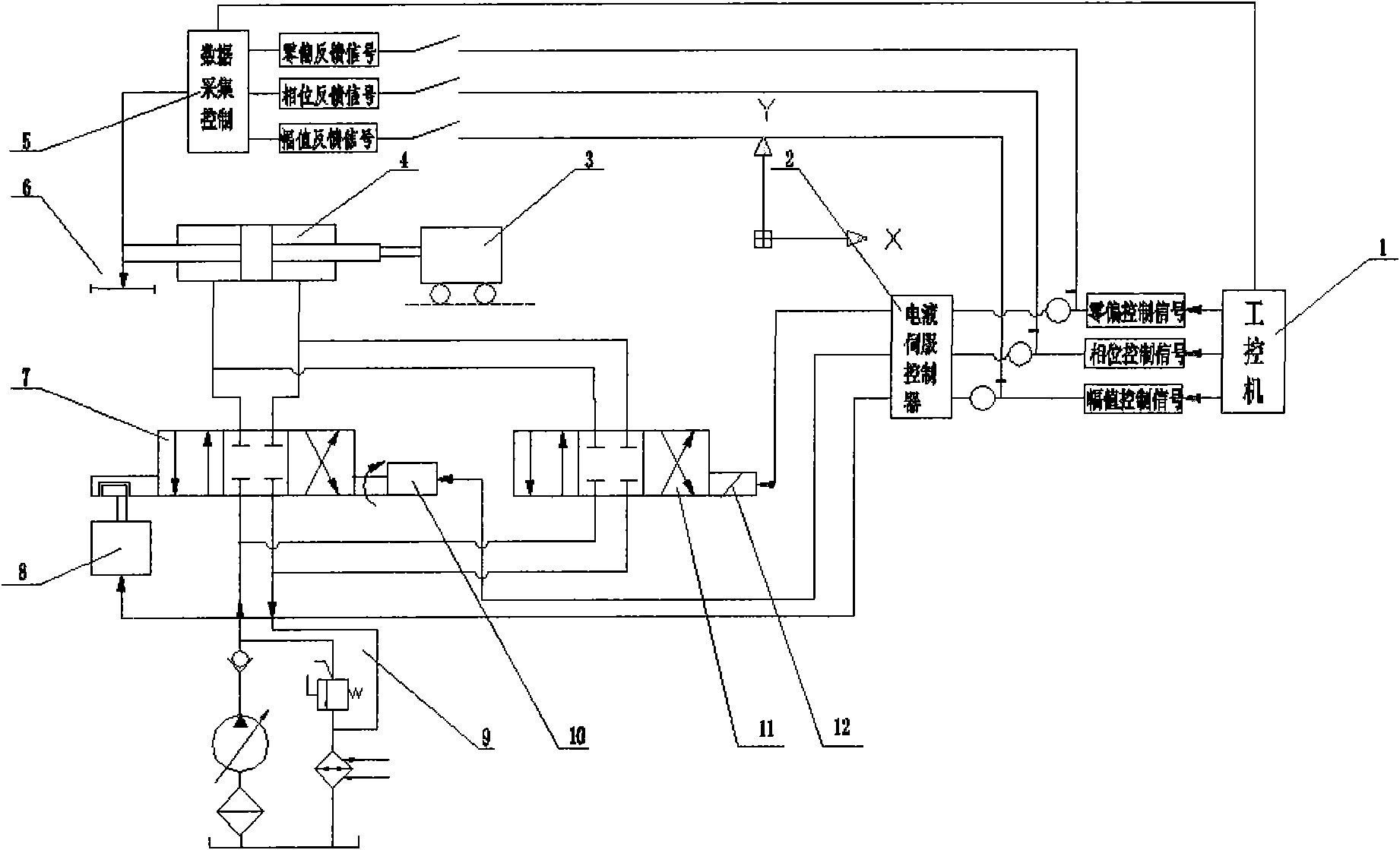
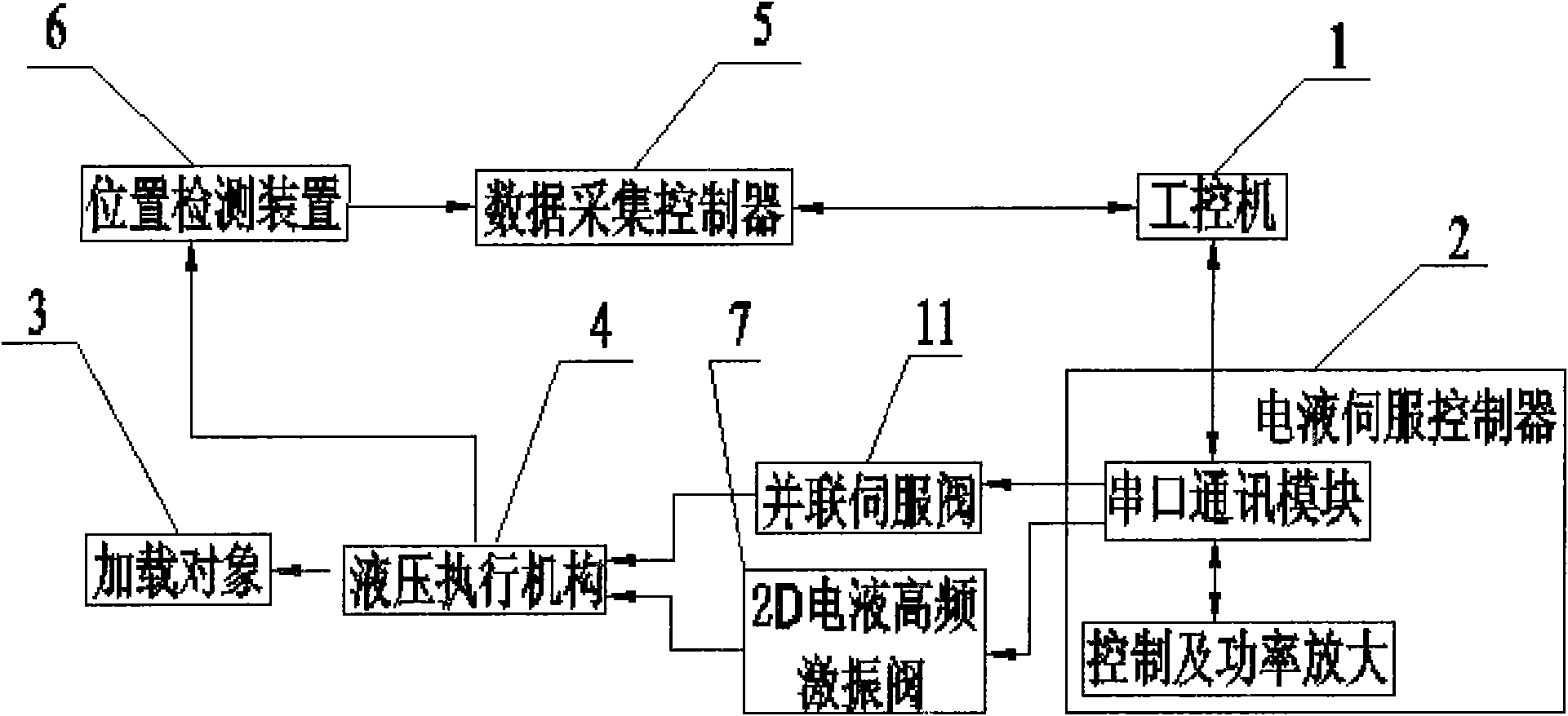
[0023] refer to figure 1 , image 3 , Figure 4 , an electro-hydraulic vibrator vibration waveform control system, including an oil source 9, a high-frequency excitation valve, a parallel servo valve 11, a hydraulic actuator 4 and a loading object 3; the oil source 9 and the high-frequency excitation valve, The parallel servo valve 11 is connected, the high-frequency excitation valve and the parallel servo valve 11 are connected to the hydraulic actuator 4, the hydraulic actuator 4 is connected to the loading object 3, and the parallel servo valve 11 includes The zero-bias servo motor 12 that controls the cam mechanism to push the spool of the parallel servo valve to slide, the high-frequency excitation valve is a 2D electro-hydraulic high-frequency excitation valve 7, and the 2D electro-hydraulic high-frequency excitation valve 7 includes An axial servo motor 10 for controlling the axial sliding of the spool of the excitation valve; the closed-loop control system also inclu...

Embodiment 2

[0036] refer to figure 1 , image 3 with Figure 4 , the 2D electro-hydraulic high-frequency excitation valve 7 of this embodiment also includes a rotary servo motor 8 for controlling the rotation of the vibration valve spool, and the rotary servo motor 8 is connected to the electro-hydraulic servo controller 2; In the control execution module, the set excitation waveform signal is also decomposed into a phase control signal; in the feedback comparison module, the phase feedback signal after decomposing the displacement waveform signal detected by the position detection device is compared with the phase control signal, And send the compared difference signal to the electro-hydraulic servo controller.

[0037] The control parameters of this embodiment also include phase, which is used to control the zero offset (average value of the output waveform), phase and amplitude of the electro-hydraulic vibrator output wave excitation waveform. The electro-hydraulic servo decompositio...

Embodiment 3

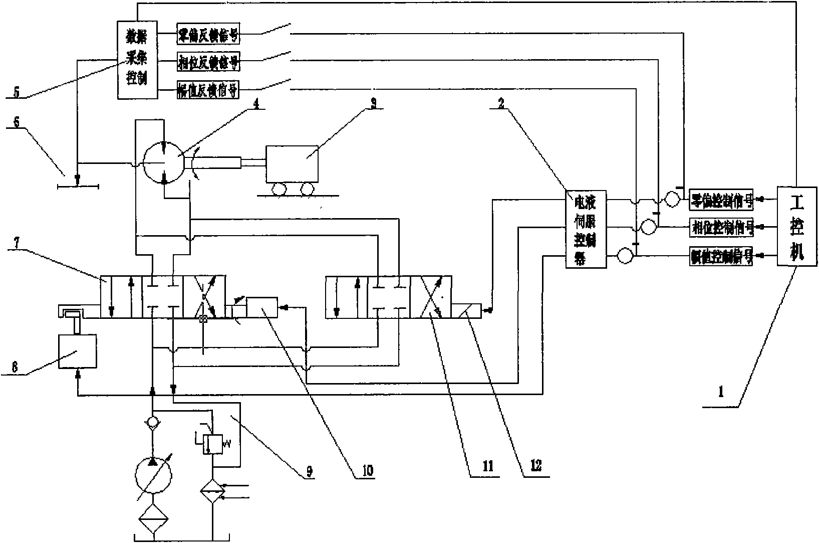
[0045] refer to figure 2 , image 3 , Figure 4 , in this embodiment, the parallel servo valve spiral servo three-position four-way slide valve structure includes a servo motor 12, and the servo motor 12 pushes the spool to slide through the spiral servo structure to control the movement of the valve core into and out of the electro-hydraulic vibration cylinder 4. The direction and size of the oil.

[0046] When the electro-hydraulic excitation cylinder 4 is a hydraulic motor, the 2D electro-hydraulic high-frequency excitation valve 7 and the parallel servo valve 11 control the piston of the hydraulic motor to rotate back and forth to make the loaded object torsionally vibrate.

[0047] The displacement detection device is an angle sensor 6, which detects the back and forth rotational angular displacement of the piston when the hydraulic motor vibrates.

[0048] Other structures and working processes of this embodiment are the same as those of Embodiment 2.


PUM


Abstract

The invention relates to a vibration waveform controlling system of an electro-hydraulic exciter, which comprises an oil source, a high-frequency excitation valve, a parallel servo valve, a hydraulic actuator and a loading object, wherein the parallel servo valve comprises a zero-bias servo motor; the high-frequency excitation valve is a 2D electro-hydraulic high-frequency excitation valve which comprises an axial servo motor; the vibration waveform controlling system also comprises a position detection device, a data acquisition controller, an electro-hydraulic servo controller and an industrial personal computer; the electro-hydraulic servo controller is connected with the zero-bias servo motor and the axial servo motor; and the industrial personal computer comprises a control execution module for decomposing a set excitation waveform signal into a zero-bias control signal and an amplitude value control signal and outputting the control signals to the electro-hydraulic servo controller, and a feedback comparison module for comparing a zero-bias feedback signal and an amplitude value feedback signal with the zero-bias control signal and the amplitude value control signal respectively and sending a compared differential value signal to the electro-hydraulic servo controller. The vibration waveform controlling system adopts closed-loop control, has small distortion degree of output waveform and high controlling precision.

Description

technical field [0001] The invention relates to an output waveform control system of an electro-hydraulic vibrator. Background technique [0002] As a basic test of modern industry and an important means of product development, vibration test is widely used in many important engineering fields, such as road simulation tests of automobiles and walking machinery; seismic fatigue tests of engineering materials, dams and high-rise buildings, etc. [0003] There are mainly three types of excitation methods: mechanical, electromagnetic and electro-hydraulic. The characteristics of the mechanical vibration table are: simple structure and low cost; There are disadvantages such as mechanical clutter. The electrodynamic vibrating table has the advantages of small waveform distortion and large operating frequency range; however, due to the limitation of inherent magnetic saturation, the electrodynamic vibrating table is not easy to obtain a large excitation force. In addition, the equ...

Claims


Application Information

Patent Timeline
Patent Type & Authority Applications(China)
IPC IPC(8): G01M7/02G05B19/04G05D3/20
Inventor 阮健贾文昂李胜裴翔俞浙青朱发明任燕
Owner ZHEJIANG UNIV OF TECH
Why Eureka
Try Eureka