

Integrated motor
A general-purpose motor and casing technology, applied in the direction of electrical components, electromechanical devices, electric components, etc., can solve the problems of complex structure, increased volume and weight, increased cost, etc., and achieve simple and compact structure, improved reliability and stability, cost reduction effect
- Summary
- Abstract
- Description
- Claims
- Application Information
AI Technical Summary
Problems solved by technology
Method used
Image

Examples
no. 1 Embodiment
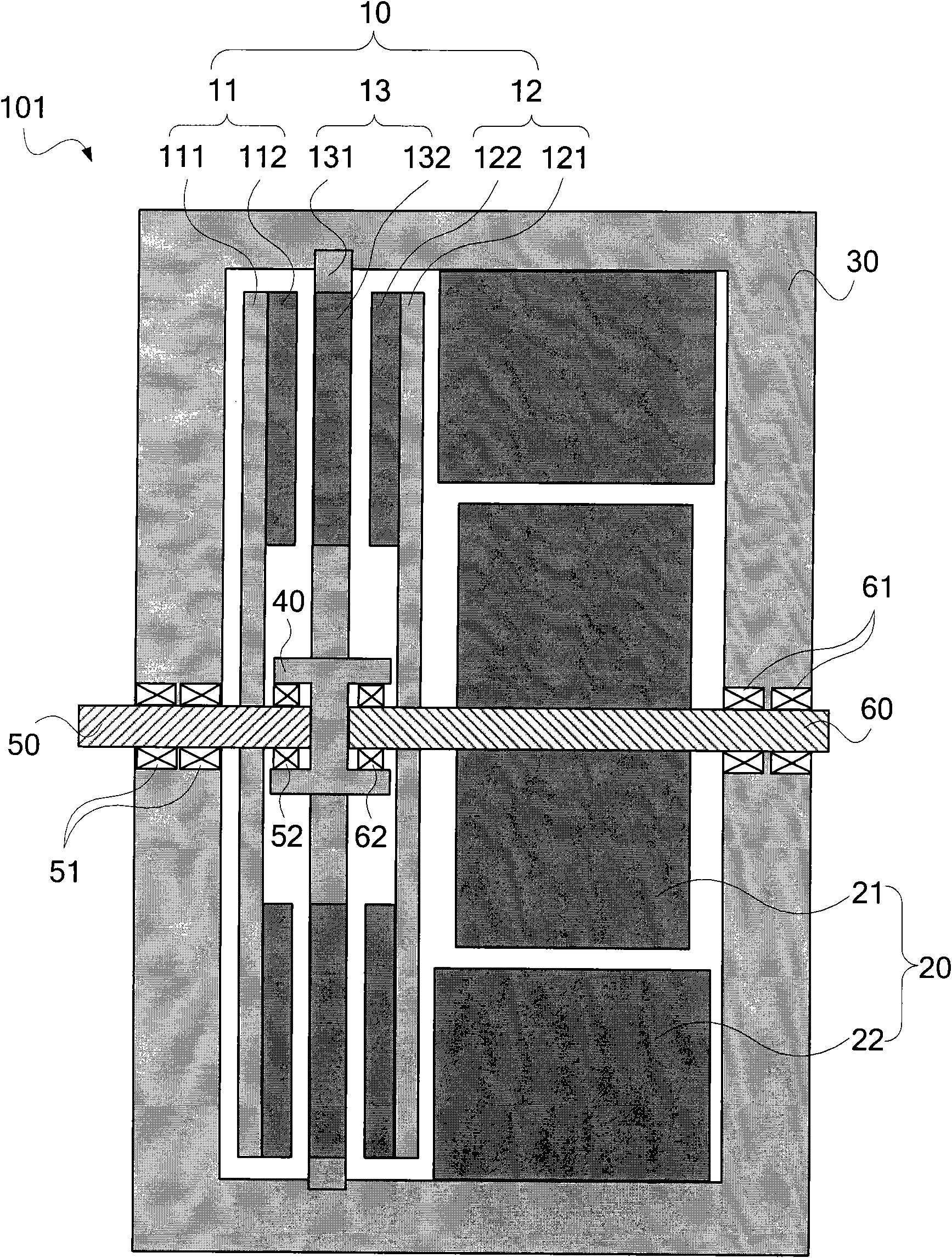
[0042] Figure 2 to Figure 6 The first specific embodiment of the integrated motor of the present invention is shown. In this specific embodiment, the integrated motor 100 is implemented as an integrated axial-flux magnetic gear (Axial-fluxmagnetic gear) and a radial-flux magnetic gear. An integrated motor 101 of a general-purpose motor (Radial-flux electrical machine).
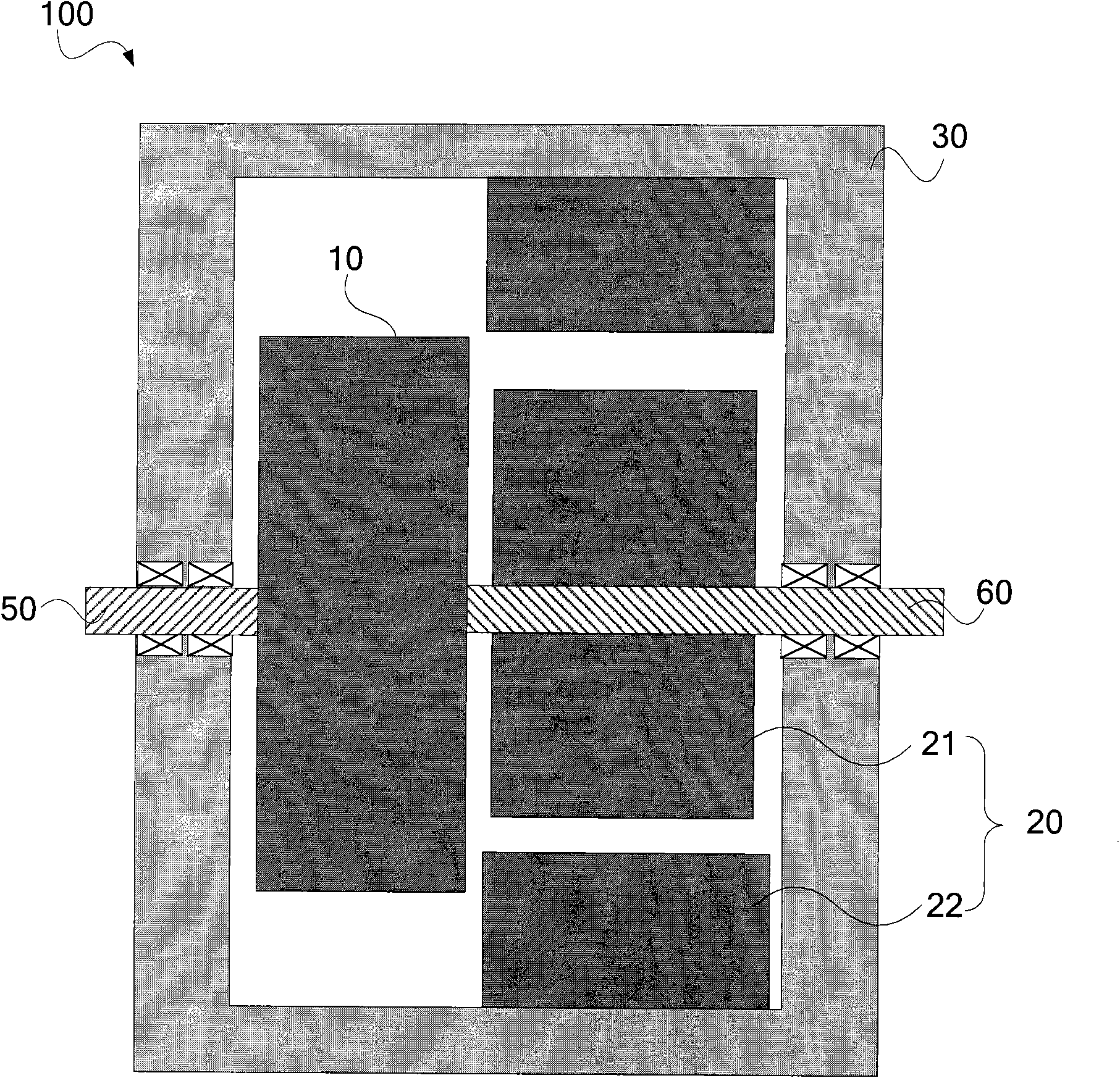
[0043] see figure 2 The integrated motor 101 of this specific embodiment includes an axial flux permanent magnet gear 10 and a radial flux general-purpose motor (Radial-fluxelectrical machine) 20 matched with the axial flux permanent magnet gear 10, and the shaft The directional flux permanent magnet gear 10 and the radial flux general-purpose motor 20 are arranged in the casing 30 .
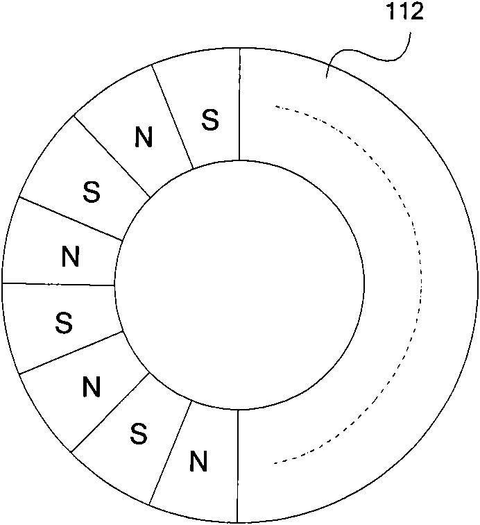
[0044] The axial flux permanent magnet gear 10 includes a low-speed rotor 11 , a high-speed rotor 12 and a stator 13 arranged axially in parallel, wherein the stator 13 is fixed between the low-speed rotor 11 and the high-sp...
no. 2 Embodiment
[0054] Figure 7 to Figure 8 The second specific embodiment of the integrated motor of the present invention is shown. In this specific embodiment, the integrated motor 100 is implemented as an integrated axial flux permanent magnet gear and an axial flux universal motor (Axial-flux electrical machine) integrated motor 102.
[0055] see Figure 7 , the integrated motor 102 of this specific embodiment is similar in structure to the integrated motor 101 of the first specific embodiment, the difference is that, in this specific embodiment, the radial flux common motor in the first specific embodiment is 20 is replaced by a dual rotor-single stator axial flux universal motor 20'.
[0056] The axial flux universal motor 20' includes a pair of rotors 21' arranged axially in parallel and a stator 22' between the pair of rotors 21'. In order to make the structure of the integrated motor 102 compact, the gap between the axial flux universal motor 20 ′ and the axial flux permanent ma...
no. 3 Embodiment
[0059] Figure 9 The third specific embodiment of the integrated motor of the present invention is shown. In this specific embodiment, the integrated motor 100 is implemented as an integrated motor integrating axial flux permanent magnet gear and axial flux general-purpose motor 103.
[0060] see Figure 9, the integrated motor 103 of this specific embodiment is similar in structure to the integrated motor 102 of the second specific embodiment, and also adopts a dual-rotor-single-stator axial flux universal motor, but the axial magnetic flux of the integrated motor 103 The difference between the universal universal motor 20 ″ and the axial flux universal motor 20 ′ of the second specific embodiment is that, in order to make the structure of the integrated motor 103 more compact, the axial flux universal motor 20 ″ One of the rotors 21' shares the back iron with the high-speed rotor 12 of the axial flux permanent magnet gear 10, that is, the back iron 211' of the rotor 21' of...
PUM
 Abstract
Description
Claims
Application Information